

This article explains how to implement a camera that is aware of the direction it is facing. Developers can use this data to enhance the user experience. This can be applied for augmented reality applications, camera based games or some interesting UI interaction; The supplied example application lets you throw baseballs at your surroundings and punch holes that stick to their real-world positions.
INTRODUCTION
This article shows how to implement a camera that has a way to determine the direction it is facing and build upon this data to enhance the user experience.
We use various sensors (namely accelerometer, magnetometer\compass and gyroscope) to determine current positioning of the device. Elements can then be added to captured camera frames thus adding Augmented Reality dimension to the application.
This article is an update to the original, published back in June of 2012. It was an entry in PureView Imaging Competition by Nokia and won an honorary mention award. The original article was targeting Symbian (s60) devices. Since the Symbian platform nowadays is pretty much obsolete, I have updated the article to target Windows Phone platform (8.1 and up). The algorithms and general idea of the application, however, can easily be ported to other platforms like Android and iPhone and if Xamarin is employed in the process this should in theory mean minimal code changes. This revision also introduces gyroscope sensor and complementary filtering which helps in getting an accurate and noiseless sensor reading that can be reliably used by the world model.
THE IDEA
To make this work we:
- Create a data model that allows the device to process positioning. With it we will be able to determine current device facing, save positions and approximate field of vision;
- Use the sensors so our data model can interact with real world;
- Employ data processing (filtering) so that we don’t rely on noisy sensors;
- Build on top of this base with our example application to add some Augmented Reality fun.
WORLD MODEL
The easiest way to imagine the data model is as a surface of a sphere (please refer to 4.1 section for a more accurate description). Any point on the surface can be determined by two coordinates, in this case we’ll call them heading and tilt. GPS uses the same idea to pinpoint geolocation.
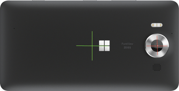
The picture below illustrates this model. If we regard the red dot in the middle of the sphere as the camera, we can see that it’s possible to tell the direction the camera would be facing with those coordinates:

To complicate things a little bit more, the camera sees a range of heading and tilt and the cross is just the center position of the frame.
This can be calculated though, provided we know the view angle of the camera, or in our terms: the vertical and horizontal angles the camera can span.
Using our model, we can also save positions and check if those are inside the angle of view.
In the picture below the orange lines indicate the horizontal and vertical camera spans. The green border denotes the whole area that can be seen.
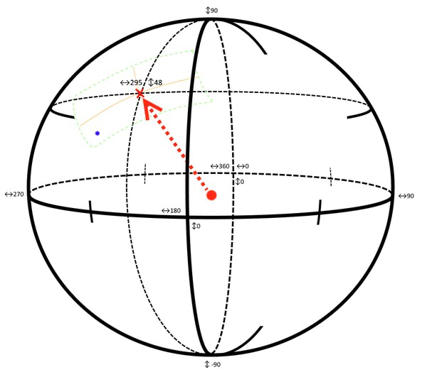
Pretty much the only thing left that needs to be done is converting the world model coordinates to screen coordinates. In the picture above the blue dot is defined by certain heading and tilt coordinates. When it falls within the viewable area we convert these coordinates to screen coordinates so that the mark is displayed in bottom left side of the screen. In the next sections, we will see how we can accomplish that.
SENSORS
To get the device positioning data we will use the set of sensors that most of current smartphones provide: accelerometer, gyrometer and magnetometer.
We use accelerometer for the most part, as it can determine the positioning of the device in all world axes but one. Accelerometer calculates the force that is acting upon the device. So, if a device was to be moved by an accelerating force in a certain direction, accelerometer would provide us with that information.
When the device is not moving though, there is still one force that is affecting the sensor: gravity. The accelerometer always detects it so we can determine the direction of the ground in regards to the device.
That is how we determine the vertical component of facing and the rotation of the device.
Accelerometer is also very prone to noise: unless it is held extremely steadily any nudge is registered as a force immediately skewing the data. To combat this, we introduce gyrometer. Gyrometer detects the speed the device is turning at, so it is in a sense an accelerometer of rotation.
One other huge shortcoming of the accelerometer is that we cannot calculate the horizontal component of facing from gravity alone. That is where the magnetometer comes in. The magnetometer sensor can detect Earth’s magnetic field, so in essence, it can act as a compass and provide us with current heading in regards to North pole. We can use .NET Compass class that wraps magnetometer nicely for us.
Magnetometer sensor, however, is easily tampered with. It requires calibration almost upon every use, it can be disturbed by nearby magnetic objects, wires etc. We will again use gyrometer to complement the shortcoming of magnetometer.
To combine the data from various sensors into three usable readings: Tilt, Heading, Rotation we will be using complementary filtering. This will allow us to filter out noises by relying on the gyrometer in the short term and getting the best of accelerometer and magnetometer in the long run.
You can read a more thorough explanation on employing complementary filter when combining sensors in my other article here.
IMPLEMENTATION
Let’s discuss the most important parts of the code.
It will be split into 3 main parts: Sensor reading, Virtual Model, and Visualizer.
Sensors Reading
The sensors reading class library encapsulates and simplifies the access to the physical sensors. For the purposes of the application we need three derived values: Tilt, Heading and Rotation. We get it by first filtering out and then combining three physical sensors on a Windows Phone device: Accelerometer, Gyrometer and Magnetometer.
We use filtering and limit the available value ranges before providing them for further usage.
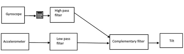
Let’s start with the simplest one: Tilt, that is – the tilt of the camera in regards to the ground.
Tilt values are in range of [-90; 90], where -90 is when camera is looking straight to the ground and 90 is up to the sky.
The value can easily be obtained from the accelerometer: the tilt directly maps to the acceleration on Z axis of the device. And can be immediately passed to be filtered for long term reliance.
For the short term, we want to plug in the values from gyroscope. The correct gyroscopic tilt must be calculated though. The value might be coming from either X or Y axis or most probably a combination of both, depending on how the device is being held.
After passing both values through complementary filter we get the pure Tilt value that we can later use.
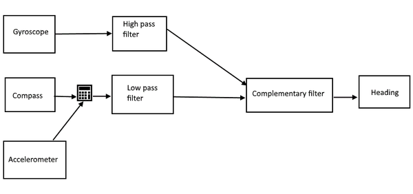
Heading is the second important piece of the positional value – it indicates the angular difference between camera center and North Pole.
Heading values are in the range of [0; 360] where 0 or 360 is looking straight North, 90 – East and 180 – straight South.
The gyroscopic heading must be calculated depending on the rotation of device as was the case with Tilt.
The compass value theoretically could be directly passed into the filtering as it indicates exactly what we need – the difference between view vector and direction of north.
[!Warning] The problem, at least, on Windows Phone Compass implementation, is that the compass value changes depending on how the device is rotated. That is: if it is held in landscape mode it returns the value you would expect; if you flip it so it’s in inverted landscape mode, the compass value changes by 180 degrees; and if device is held in portrait mode the angle increases by 90 degrees. To combat this behavior, we have the NormalizeCompassHeading method. It keeps track of sudden changes in heading and adjusts the value depending on the calculated state. You can read more about this in 4.2 section.
Rotation indicates how much the device is rotated on the camera view vector.
Rotation values are in the range of [0; 360]. Where 0 or 360 is when the device is held in landscape mode with buttons to the right; 90 is portrait mode with buttons at the bottom and so on.
The gyroscopic rotation is really easy this time around: it directly corresponds with gyroscope Z axis (albeit inverted);
The reliable accelerometer value can be also easily acquired once we calculate the angle between two vectors: V (accelerometerX, accelerometerY) and V(-1, 0) that is the landscape mode buttons on the right acceleration values vector.
Value Wrapping
One more additional technique to take notice of is the wrapping of ranges. For example, when compass is moved full circle the ranges don’t go above 360 – they wrap around back to 0. In the same sense when we want to know the angle difference between two values we need to consider the wrapping. For example, if we had angle values of 30 and 310 the difference would be 80 degrees since we take wrapping into account. When calculating difference, we always take the lower of two resulting angles.
Virtual Model
To be able to create and save view augmentations that react correctly when brought into view, we will need a data model that can support all the required behavior.
Augments
Augment or augmentation, is an entity that overlays real world elements to supply additional information about that specific viewable area.
In our case, we don’t need much. All augments will be behaving the same way and the only difference between instances will be their position and the “animation” state. For that we have a data class that contains the Position (Heading and Tilt) where the object resides. It also has a flag to indicate that the augment has hit the wall which indicates a change of state in animation.
World Model
The world model is the main control hub for all the business logic:
- It has the list of all the created augments;
- It has access to the sensory aggregate which gives it information of current positioning of the device;
- It also has access to projection calculator which has facilities to filter augments and map model coordinates to screen space.
In summary, what world model is responsible for is:
- When ball is being launched, it gets current positioning of the device and saves it to the list of active augments
- When a new Update cycle is requested, it filters all the active augments so only the ones that are within the visible camera angles are drawn; then it recalculates each of their world model positions to screen coordinates per current direction and rotation of the device.
Projecting world model onto screen space
In order to properly display augments over the camera image we will need to project the world model augment coordinates described by Vector(Heading, Tilt) to screen coordinates described by Vector(X, Y). This means taking in the current camera position and adjusting the saved augments accordingly so their positions can be properly mapped and drawn onto screen.
To help us with all the math heavy calculations we have the ProjectionCalculator and MathHelper classes. In there we have quite a few methods for various common calculations like normalizing angle with NormalizeAngle or getting the angle between two vectors with CalculateAngleBetween2Vectors. But the ones that need to have a separate look at are the GetDistanceFromCenter, RecheckForWrapping, ProjectPointPosition, and IsPointWithin methods.
RecheckForWrapping is probably the clearest of them all: it takes in a saved augmentation position (point) and rechecks its position against the current camera position and camera angle span.
This is done in case we end up with a scenario where the saved point is at one extreme, say 174° heading and the camera center points at the other extreme, say -178° (angle normalization ensures that all angles are in the range of [-180°, 180°] ). In this case, we have a wrapping issue where all sensible calculations think the difference between the two is 352° when it actually is a mere 8°.
So, with this method we check for cases like that in horizontal and vertical ranges and adjust the provided point to be in accordance with the camera position, allowing them to go over the [-180°, 180°] ranges if needed, so the calculations can proceed normally.
A minor adjustment to the formula is when we work with Tilts: the wrapping values are quite near each other so we deliberately set a higher precision gate.
private static Position RecheckForWrapping(Position point, Position currentCameraPosition,
										   Position cameraAngleSpan)
{
	Position adjustedPoint = new Position(point.Heading, point.Tilt);
	if (IsResultingHeadingOver180(currentCameraPosition, cameraAngleSpan))
		if (point.Heading < 0)
			adjustedPoint.Heading = Math.PI * 2 + point.Heading;
	if (IsResultingHeadingBelowMinus180(currentCameraPosition, cameraAngleSpan))
		if (point.Heading > 0)
			adjustedPoint.Heading = -Math.PI * 2 + point.Heading;

	if (IsResultingTiltAbove90(currentCameraPosition, cameraAngleSpan))
		if (point.Tilt < 0)
			adjustedPoint.Tilt = Math.PI + point.Tilt;
	if (IsResultingTiltBelowMinus90(currentCameraPosition, cameraAngleSpan))
		if (point.Tilt > 0)
			adjustedPoint.Tilt = -Math.PI + point.Tilt;

	return adjustedPoint;
}
IsPointWithin on the other hand is probably the most difficult to get your head around with since it is extremely math heavy. What it does, in essence, is take the saved augmentation position and current camera view description defined by cameraTarget (Heading and Tilt), camera angle spans and the rotation of the camera and determines if the said augmentation position is visible within the current camera view.
The actual calculation assumes that the viewable area is defined by a View Rectangle. View rectangle is a rectangular area that is viewable by your camera viewfinder and it is defined by four corner points. The complexity here arrives with the fact that this rectangle is not necessarily always sitting perpendicular to the floor, that’s why I have taken the route of defining the rectangle with four separate points. On the side note the algorithm could be reused to check if the point is within any four point (or more) convex shape with minimal changes.
To construct the view rectangle’s corner points, we use the current camera center target position and its angle spans adjusted by rotation to get the outermost viewable corners.
The check itself divides the view rectangle into 4 triangles, with a shared vertex – the point that is being checked. The area of one triangle is determined by this formula (where vertical bars represent the determinant):
      1 | x0 y0 1 |

  A = - | x1 y1 1 |,

      2 | x2 y2 1 |
The queried point is within the view plane only when all 4 triangles have the area that is either negative or positive in all of them. You can check out the theory behind the algorithm and its other variations HERE.
private static bool IsPointWithin(Position pointPosition,
								 Position currentCameraTargetPosition,
								 Position cameraAngleSpan,
								 double angle)
{
	var camAngleSpanH = cameraAngleSpan.Heading;
	var camAngleSpanV = cameraAngleSpan.Tilt;

	double cameraHeading = MathHelper.NormalizeAngle(currentCameraTargetPosition.Heading);
	double cameraTilt = currentCameraTargetPosition.Tilt;

	//create a viewplane rectangle using current center point and camera angle of view
	Position[] rectangleO = new Position[4];
	rectangleO[0] = new Position(cameraHeading - camAngleSpanH / 2, cameraTilt - camAngleSpanV / 2);
	rectangleO[1] = new Position(cameraHeading + camAngleSpanH / 2, cameraTilt - camAngleSpanV / 2);
	rectangleO[2] = new Position(cameraHeading + camAngleSpanH / 2, cameraTilt + camAngleSpanV / 2);
	rectangleO[3] = new Position(cameraHeading - camAngleSpanH / 2, cameraTilt + camAngleSpanV / 2);

	//rotate all four corners of the rectangle around the center (if camera was not held perfectly flat)
	Position[] reactangleR = new Position[4];
	for (int i = 0; i < 4; i++)
	{
		Vector originalV = new Vector(rectangleO[i].Heading, rectangleO[i].Tilt);
		Vector rotatedV = Vector.RotatePoint(originalV, new Vector(cameraHeading, cameraTilt), angle);
		reactangleR[i] = new Position(rotatedV.X, rotatedV.Y);
	}

	//check if the given point is within the viewplane rectangle
	double pointHeading = pointPosition.Heading;
	double pointTilt = pointPosition.Tilt;

	bool pointWithin = false;
	int expectedSign = 0;
	for (int i = 0; i < 4; i++)
	{
		int i0 = i;
		int i1 = (i + 1) % 4;
		double A = 0.5f * (reactangleR[i1].Heading * pointTilt - reactangleR[i1].Tilt * pointHeading
						   - reactangleR[i0].Heading * pointTilt + reactangleR[i0].Tilt * pointHeading
						   + reactangleR[i0].Heading * reactangleR[i1].Tilt
						   - reactangleR[i0].Tilt * reactangleR[i1].Heading);
		if (i == 0)
			expectedSign = Math.Sign(A);

		//check and break out if the values don't correspond. neat little trick
		if ((A >= 0 && expectedSign >= 0) || (A < 0 && expectedSign < 0))
		{
			if (i == 3)
				pointWithin = true;
		}
		else break;

	}

	return pointWithin;
}
ProjectPointPosition the method that does the actual mapping from World Model to Screen Coordinates.
It prepares the augment in question by rotating it backwards (to where it would end up if the device was not rotated at all) for easy projection. Then we remove the offset by subtracting the camera position from the position of the augment itself and adjusting it by view angles. Finally, we get the relative positional ratio to the view angles by dividing each component by the appropriate view span component. What we get in the end is the point mapped to Vector coordinates that each fall to the range of [0, 1]. If we later multiply these by the screen dimensions we end up mapping the augment it to any screen size, we might come across.
private static Vector ProjectPointPosition(Position pointPosition, Position currentCameraTargetPosition,
											Position cameraAngleSpan, double angle)
{
	var pointPositionV = new Vector(pointPosition.Heading, pointPosition.Tilt);
	var currentCameraTargetPositionV = new Vector(currentCameraTargetPosition.Heading,
												  currentCameraTargetPosition.Tilt);

	//rotate point backwards for easy projection
	var rotatedPoint = Vector.RotatePoint(pointPositionV, currentCameraTargetPositionV, -angle);
	var pointNoOffset = new Vector(rotatedPoint.X - currentCameraTargetPosition.Heading + cameraAngleSpan.Heading / 2,
								   rotatedPoint.Y - currentCameraTargetPosition.Tilt + cameraAngleSpan.Tilt / 2);
	var finalizedPosition = new Vector(pointNoOffset.X / cameraAngleSpan.Heading,
									   1 - pointNoOffset.Y / cameraAngleSpan.Tilt);

	return finalizedPosition;
}
GetDistanceFromCenter is sort of the main control method that combines all the data processing into one fluent orchestration.
It first uses the before mentioned methods to normalize angles, check for possible value wraps and check whether the point in question is currently visible. If all is green, it immediately calls ProjectPointPosition to perform the coordinate mapping.
private static Vector GetDistanceFromCenter(Position point, Position currentCameraPosition,
											Position cameraAngleSpan, Position cameraAngleSpanRotated,
											double cameraRotation)
{
	var pointN = RecheckForWrapping(point, currentCameraPosition, cameraAngleSpanRotated);

	var pointProjection = new Vector(-3, -3);
	if (IsPointWithin(pointN, currentCameraPosition, cameraAngleSpan, cameraRotation))
		pointProjection = ProjectPointPosition(pointN, currentCameraPosition, cameraAngleSpan, cameraRotation);

	return pointProjection;
}
Visualization
The Visualization is where we implement our actual demo application. What our demo application will do is:
- display in full screen what is currently seen via viewfinder. In the middle, we will draw a crosshair
- if the user touches the screen, the camera will “throw” a baseball at that middle position which after a second or so will “hit” whatever was there and draw a hole decal over it to indicate some persistent damage marking
- if at any point in time we move the device around, the holes or baseballs that are still in-flight, will keep to their “real world” position to provide that augmented reality feel.
Most of this is already implemented in the world model. What we will need are only the visual parts (hence Visualization) that react on changes to the world model.
WPF Tree
Let’s take a quick look at the Main Page’s WPF tree.
On the top level, we have the main grid that contains all the other elements and has the responsibility to react to screen taps.
Inside there is the CaptureElement element, whose sole responsibility is displaying camera’s feed onto the screen.
Next we have the Canvas that will contain all the augmented marks. We use Canvas element so that we can position its child elements with absolute coordinates. Also, there is a static Image being immediately added onto the Canvas that displays the crosshair in the middle of the screen (more on that later).
Lastly we have a StackPanel that contains three TextBlocks that will be used to output relevant data. Reliability shows how accurate Magnetometer measurements currently are. And ConsoleOut is just for quickly outputting any needed debug data directly on screen. Feel free to use that for your own needs.
<Grid Tapped="UIElement_OnTapped">
	<CaptureElement  Name="cameraView" />
	<Canvas Name="markOverlay" >
		<Image Source="Assets/Crosshair.png" Name="crosshairImage" Width="75"></Image>
	</Canvas>

	<StackPanel >
		<TextBlock Text="Reliability"/>
		<TextBlock Text="{Binding Reliability}"/>
		<TextBlock Text="{Binding ConsoleOut}"/>
	</StackPanel>

</Grid>
Code Behind
There is some code behind in the MainPage to make the life a bit easier and so that the project is not overcomplicated in the unnecessary areas.
The MainPage’s constructor in addition to default initialization also fires off initialization of the augmented camera elements:
- spins up an AugmentedCamera instance which in turn will initialize the WorldModel, sensors, etc.
- configures and starts the update timer.
- repositions the crosshair image to be in the center of Canvas.
It also has an event handler that starts the launch of the ball augment.
Finally, it contains the UpdateTimerTick event handler. It first measures the elapsed time between the calls and uses it to update the WorldModel (progress ball animations and update current position of camera\augments).
Camera Capturer
The camera capturer is there to encapsulate the interactions with the hardware camera.
When it is initialized it enumerates through all the cameras in the device and selects the “main” one.
It also provides a method to start the capture by directly binding onto the UI element that was provided with the constructor.
Augmented Camera
The AugmentedCamera serves as the connecting hub of all the visualizer elements and the WorldModel.
The two main points of interest here are the camera angle processing and UpdateAugments method.
At the top of the class we have the camera angle constants. It defines the horizontal and vertical view ranges of the camera aperture. You can read more about the specifics of device camera angles in section 4.6.
The UpdateAugments method uses the camera view ranges to get augment filtered and mapped to screen coordinates. It requests the visible augments list from the WorldModel and passes it to the visualizer so it can be drawn out.
Visualizer workings
At the heart of visualization, we have the Visualizer class. It contains two methods to create Image elements to draw out the holes and balls augments. The ball augment is created when the screen is tapped and the ball is launched. After a set amount of time passes it morphs into a decal on whatever it hit.
The DrawAugments method uses the visible augment list to display all the augmentations that can currently be seen on screen. The augmentations that move out of view get their corresponding Image elements in the dictionary marked as hidden. If it is a new augmentation, we create a new Image element using the methods mentioned before and add it to the dictionary tied to that particular Augmentation instance. In case the augmentation morphs from a ball to a hole, the Image element gets replaced with a new one in the dictionary.
CONSIDERATIONS, LIMITATIONS AND IMPROVEMENT POINTS
In this section, I’ll shortly describe the areas of the application that were left out or could be considered the first candidates for improvement if the application is to be developed further.
Cylindrical model
Even though throughout the article the model was referred to as a sphere, in reality it is more of a tapered cylinder:
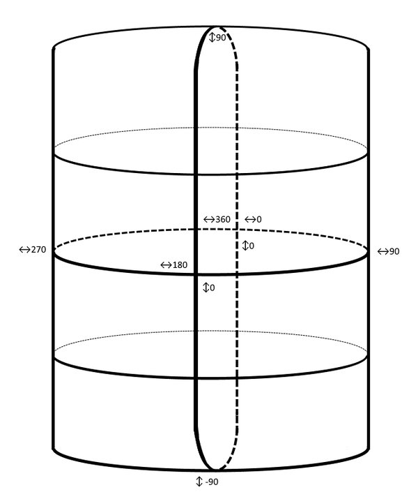
It is quite difficult to explain it even via visual image as in reality this model is an impossible
object (think Penrose triangle). I’ll try my best to describe the qualities of it so you should be able to visualize it in your mind.
With the current implementation, there is big limitation with the tilt value wrapping. When the values go over 90 the values don’t wraparound to 0 like we do with heading rotations. All values over 90 start diminishing the resulting value so it wraps around the sphere nicely. For example, 96 degrees should map to 84.
It should also start to converge once the values are getting closer to the poles: for example, all augmentations that are on 90 or -90 tilt are to be displayed on the same spot regardless of their heading. Or if camera is looking straight down, it should be able to see all augmentations with headings -180 to 180 if their tilt value falls within respectable view angles of the camera.
With the current World Model implementation, this happens only to a very limited extent.
These are the limiting factors that should be addressed but can be ignored if the camera application will mostly be used to indicate distant directions in a vertical space and mostly will not be used when “looking” straight down or up.
Compass sensor data acquisition improvement
For the testing of the sample application I was using my Microsoft Lumia 950 device. When the device is asked to provide the Heading of the device, the returned value is actually being influenced by the positioning of the device.
For example, if the device is pointing straight at North (so, heading 0) when held in a landscape position, and then is rotated into portrait or inverse portrait mode, the heading will at some point suddenly jump by an offset of 90 or negative 90 respectively.
What is currently being done to combat this behavior, is tracking of heading and regarding sudden changes as a change in state, subtracting or adding the offset so there are no sudden gaps or jumps in heading when the device is rotated.
The worst part about this approach is that it assumes the device is being held in the “default” landscape position when the application starts up. Otherwise it mixes up the order of states and this in turn might mess up all the calculations. It is also in theory possible to rotate the device in such a way that it might change from landscape to inversed landscape causing the current state to change into wrong one.
This could be improved by encapsulating all offset adjustments within the compass sensor to have a consistent reading regardless of the device position. This could be achieved by employing other sensors to get the current state by absolute means.
I am not certain if this is the case with other brands, like Android or iPhone, so this limitation should be addressed accordingly on those platforms.
Spatial positioning
Probably the biggest limitation of this application (even worsened by the fact that it is limiting at the conceptual level) is the spatial positioning of the device.
The application works normally as long as the device stays completely nailed to the starting point in space: the device can be rotated in any way, but the center of the lens or, more specifically the center of CCD\CMOS sensor cannot change its altitude, longitude and latitude (or XYZ positions if you will) by even a fraction.
It is possible to approximate the spatial positioning by getting data from the sensors. The problem is that all three of them (gyrometer, magnetometer and accelerometer) will only get you that far as you will be integrating movement forces over time and this will inevitably introduce bias and will quickly become noticeable. You could in theory get the absolute positioning at any point in time by using altimeter and GPS sensor. The problem with these is that altimeter is not necessarily present on the device (or the altitude GPS component is not provided by the GPS sensor), and the GPS sensor is not nearly accurate enough (with the best GPS sensors boasting an accuracy of 3 meters, though the user will be noticing discrepancies at changes within centimeters) and it does not work inside buildings.
With the rise of research and devices in the realms of Virtual Reality (VR) and Augmented Reality (AR) in recent years we know it is possible to be spatially tracked by external means. For example, Oculus Rift and HTC Vive accomplish this by having sensors or infrared cameras positioned around the room which when calibrated can calculate the person’s spatial position accurately enough so not to break the immersion.
Sadly, this is not the case with current generation mobile devices, so the only possible means to deal with it is: limiting the user with not moving the device, put up with the rising bias from the sensors onboard or live with the limited accuracy of spatial GPS sensor.
One final point to make is: the farther into the distance the augmented objects are, the less relevant spatial positioning becomes. So, if the application for example, is showing important landmarks that are hundreds of meters or kilometers away, it is easily correctable by absolute positioning of GPS sensor.
Camera center v. Screen center
One problem I came across and that took me some time to realize what was happening when testing the application was the difference between camera center and screen center.
I was using Microsoft Lumia 950 device (and it is the case for most smartphones these days), which has the camera way to the side of the device itself. This means that whatever you see in the center of your screen in reality comes from the side of it. So, if you wanted to rotate the device by keeping the very center of the image still you would need to rotate it around the center of the camera (which, again is on the side of the device), not the center of the device itself.
This is really, and I cannot stress it enough, really, counterintuitive for the user. While I was developing the application, I wasted quite a few hours looking for the bug: augmentations were not moving to the correct spots when the device was being rotated, only to realize that I was always rotating by what I was seeing – the crosshair which was in the middle of the screen. This could maybe be mitigated by moving the crosshair to the position of the camera lens, but you would be tailoring towards specific devices and it would still feel cumbersome. Of course, this would not be the problem if the device had a camera in the dead center of the device.
Magnetometer calibration
Magnetometer sensor is a bit different from all the other ones is that it needs to be calibrated to give out accurate readings.
On a Windows Phone the Compass class provides its event handler with CompassReadingChangedEventArgs argument. It has the HeadingAccuracyproperty which tells you how reliable the provided reading is.
To fully calibrate the magnetometer, the device needs to be moved in a figure 8 (or more accurately – following Möbius strip as pictured below) until the maximum reliability rating is reached.

It is always a good idea to provide the user with a calibration screen that tells the user how to calibrate his\her device and showing increasing reliability as you go.
Camera angles
One of the trickier parts is dealing with the camera view angles. The angles provided in the constants of AugmentedCamera class are custom tailored to work with Microsoft Lumia 950 back camera aperture.
Those were first calculated by drawing the view plane edge points onto paper and finding the horizontal and vertical angles and then by trial and error adjusted to the values that worked best.
It is quite hard to recommend any failproof way to get the camera angles automatically. It could be done if there was a database of all devices and their camera view ranges, or if the application had a calibration page that asked user to rotate the camera until the same spot that was at the very edge of the left (top) side of the screen reaches the very edge of the right(bottom) side of the screen.
Probably the easiest method is by taking a photo of a ruler, then measuring the distance from the camera distance to the ruler and then calculating the angle with a bit of trigonometry.
In any case this topic should be researched further as otherwise the application is immediately limited to one specific device model.
Ending notes
This article explained how to use the sensors that are present on most smartphones these days to implement a camera that can detect the direction it is facing. We have employed sensor filtering to filter out noisy sensor data, implemented a world model to save location of the augmentations and written a fun little test application that lets you play with your real-life environment by adding augmented reality markings.
I hope this article inspires you to come up with some cool ideas and implementations or gives you that very needed push in the application you were struggling with. Please share anything you come up with in the comments and social media.
You can find the source for the project in my gitlab repository