
The article covers the creation of a 3D Direct3D rendered maze for UWP (so that it could be run on any of Microsoft’s platforms – Windows 10, Windows Phone (Windows 10 Mobile), Xbox One or HoloLens) and it is navigable with voice commands.
The application starts with the player’s avatar positioned on the starting tile indicated by a black ‘S’ letter. The user uses voice commands (or the corresponding directional inputs with arrow keys): “up”, “down,” “left” or “right” to guide the avatar through the maze to the finish tile indicated by a white ‘F’ letter. After reaching the finish, a short winning animation is played, through which everything is reset back to the start state for another round.
This is an update of my previous article titled “Writing a 3D DirectX maze that’s navigable with speech commands” which was written in commemoration to the arrival of Windows Phone 8. In addition to many new features brought in by the platform update developers then were provided with the ability to write and run native applications on WP8 devices. The article targeted DirectX 11 for Windows Phone 8 platform.
This current article updates the technologies used in the original article to their latest counterparts. The accompanying code sample is also structured in a way that in my opinion would be the best starting point for easy customization and building of your own engine\game.
So, buckle up and let me take you on a bumpy journey to the shallow parts of the deep oceans of DirectX.
REQUIREMENTS
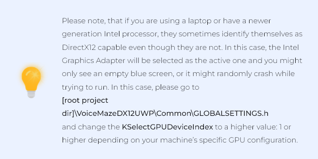
To run the sample, you need a Windows PC running Windows 10 with a DirectX 12 ready GPU.
For a comfortable reading experience, you need to have a working knowledge of C++.
Previous DirectX knowledge will ease the process a lot, but it is not a must.
I strongly recommend downloading HLSL Tools by Tim Jones. This will significantly enhance the experience when dealing with shader code.
RUNNING THE SAMPLE
The first step would be to try out the application in action.
During the first run of the application, you will be prompted to allow the application to access the microphone. Select ‘YES’, so that the application would be able to initialize speech recognition engine and you would be able to navigate the maze by shouting commands into your computer’s microphone \ camera.

In the Windows prompt, please allow the use of the microphone for voice input
Here you can see the application in action:
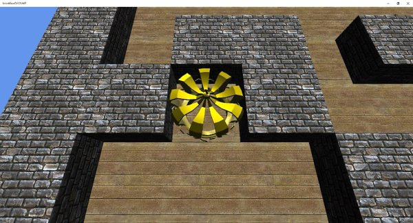
| App in action |
1. DIRECT3D 12
The subset of DirectX 12 API known as Direct3D 12 is used to deal with 3D rendering.
The thing with Direct3D 12 is that it is really different from all the other recent releases of D3D. Many of the things that used to be handled for you by the driver is now your responsibility. Now you can optimize for far better performance by having more control over multithreading and the possibility to offset more work onto GPU. This, in turn, will free the CPU for other tasks.
Sadly, it comes at a price of hugely increased complexity. DirectX had always carried the reputation of being a hard and involved API to work with. With DirectX 12, even developers, who already had previous run-ins with D3D, might be shockedby the difference in the approach of D3D12. I can only imagine how it is for complete newcomers (or actually, those guys might be at an advantage as they will not need to “unlearn” the previous knowledge). The removal of immediate drawing and emphasis on indirect drawing via command lists, descriptor tables, pipeline state objects, etc. have changed the rules of the game a lot. One might even find that correctly initializing the state of the device for a simple drawing operation might prove to be a challenge. This also means you will have to adjust the architecture of your project accordingly to get the most of the new API.
I had quite a struggle and was questioning pretty much every decision Microsoft has made with this new version of Direct3D. The Direct3D 12 brings in breaking changes, especially when you compare the two architectures that you would end up with when employing this and the earlier versions.
The thing to remember here though is that this was all done for the greater benefit. If you press forward regardless of how hard and frustrating it gets, eventually you will reach a point where you will feel comfortable with the codebase again, and at this point, you will have made the foundation that is much more performant and flexible than any previous version would have allowed it to be.
I have tried to do my best to allow the sample project to be a launchpad, a mini(micro(nano)))-engine of sorts, that would let my readers understand how certain common things are achieved in DirectX12 and build upon that newly found knowledge by extending the sample to their needs. You might be surprised, but by creatively using the building blocks that currently reside in the sample project, you could create a working game even though it would be missing some parts like, e.g., shadow casting.
2. STARTING UP
We will be starting with C++ DirectX 12 UWP project template structure. If you select DirectX 12 App from templates when creating a new project in Visual Studio, you will get a project that is exactly that.

| Select the “DirectX 12 App (Universal Windows)” template for a fresh DirectX enabled starting point |
It already provides us with a gritty, low-level initialization and operation functions. We already get basic things like graphics device selection and initialization, swap chain setup, depth buffer creation, resource fencing, frame buffering, etc.
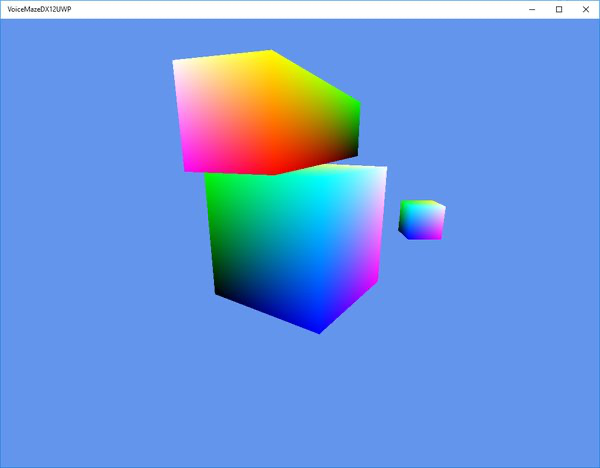
And if you just run it, you will get a fully working DirectX app: the state is initialized, geometry is rendered and also update calls are made. Just by doing that you get a signature spinning “rainbow cube” on a “cornflower blue” background. As per tradition.
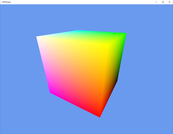
| Running the template project already provides you with a rendering “rainbow cube” |
Now to start things off – we will immediately remove random stuff left and right. No, on a serious note, all of the “game” logic, when starting with the template, is contained within Sample3DSceneRenderer class. And I mean all kinds of things – game specific initialization, transformations, projections, game (update) logic, rendering, you name it. It’s a mess, albeit, it’s an example that you are supposed to rewrite it anyway. I would like to propose more structure and explicit responsibility bounds so that the project is easier to navigate and maintain.
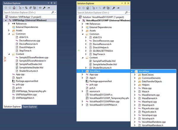
| The screenshot indicates which parts were removed from the template |
The idea is as follows: the Sample3DSceneRenderer class was removed and the contents (or their enhanced counterparts) were all moved to various classes within VoiceMaze folder.
Camera class accommodates the view transformations.
Renderer3DBase takes most of the initialization logic and provides a generalized game loop (this class is expected to be extended by another class with concrete implementation for the particular game logic, as in this case is VoiceMazeRenderer).
RenderableObject is a base where the setup of the renderable object (the “rainbow cube,” for example) happens.
GLOBALSETTINGS is just that – global project settings like GPU adapter skip index or content base directory.
I tried to keep the DeviceResources file as much intact as possible. It only has minor adjustments for the GPU adapter skip regarding the problem that was mentioned earlier.
For more details look at the General code\engine structure
3. BASIC 3D DEVELOPMENT CRASH COURSE
In this section, I will do a quick general introduction to DirectX and 3D development principles before moving to the sample application – Voice Maze.
So, if we start with the template application, there are a few essential things that are happening already. Namely:
- the content is being initialized
- the game loop is being run
- certain transformations are being applied every frame
- shaders are being executed
3.1 Initialization
One of the nice things that DeviceResources already supplies us with is the graphics adapter initialization. There is, of course, the selection of the correct hardware (since most of the computers nowadays have both processor integrated and a dedicated graphics card). But it does not stop there.
It also creates other essential elements: it initializes descriptor heaps that are later used for the render target and depth stencil.
The synchronization objects, also known as fences, are initialized here too. This together with resource barriers binds to the multithreading management of DirectX 12. Fences mark when specific work has been finished by GPU or CPU so that they could be synchronized. Resource barriers add commands to perform conversions between resource types (for example from a render target to a resource).
After that, we perform the swap chain initialization. The main purpose of the swap chain is to provide a safe way of updating the data that is currently being displayed on the user’s monitor. If, say, the application was to send all its render output straight to the monitor, the user would see a lot of drawing artifacts because of the out of sync update rates. For example, if the update rate of the monitor is 60Hz and your application on this particular machine manages to output 100 frames every second, this means that there is quite a high possibility that a single display refresh will consist of the data from 1.6 frames. This happens because once half of the image gets displayed on the screen the data of the new frame arrives and monitor immediately starts pulling the rest of the image from this new, replaced data. This ends up in visible artifacts. Depending on how fast the visuals change on the screen and the disjoint between monitor refresh rate and FPS, the effects range from barely noticeable to quite distracting. One of the most familiar ones that you might have encountered is screen tearing.
To mitigate this, we use the swap chain: we write to an invisible buffer and as soon as that one is filled, we swap it with the one being displayed. We can use double or even triple buffering for this. And all that functionality is already provided inside the DeviceResources.
Then we create the render target views. These are the actual draw surfaces we will be using to render to, and they will get swapped around by the swap chain.
Lastly, we are provided with the depth stencil. The depth stencil has a very specific role in 3D development. This buffer is used to sample if a specific geometry is in front or if it is actually being blocked by other geometry when viewed by a virtual camera. If the depth stencil is not used properly, the geometry might not sit quite right or render completely weirdly.
3.2 The initialization code
Now we will look at the main parts of the code that was moved from Sample3DSceneRenderer to other classes. Most of the initialization was moved to Renderer3DBase class. This class is supposed to be extended by a concrete Renderer implementation that executes all the game-specific logic.
3.2.1 Root signature
The first big one is root signature. A root signature is a descriptor that the app fills in, and it links to the resources that the app will use in the shaders. Root signature can contain three parameter types:
- root constants – for small rapidly accessed data. They are limited in number
- root descriptors – these are again for often accessed resources and are limited to CBV (constant buffer view), SRV (shader resource view), UAV (Unordered Access view). We will be using these for per-frame and per-object constant buffers.
- descriptor tables – which have two indirections so are a bit slower but are unlimited albeit a bit more complicated to use. We will use it for texture descriptors.
D3D12_ROOT_DESCRIPTOR rootCBVDescriptor;
rootCBVDescriptor.RegisterSpace = 0;
rootCBVDescriptor.ShaderRegister = 0;

CD3DX12_ROOT_PARAMETER rootParameters[3];
{
	CD3DX12_DESCRIPTOR_RANGE range;

	range.Init(D3D12_DESCRIPTOR_RANGE_TYPE_CBV, 1, 0);
	rootParameters[0].InitAsDescriptorTable(1, &range, D3D12_SHADER_VISIBILITY_VERTEX);
}

{
	CD3DX12_DESCRIPTOR_RANGE range;

	range.Init(D3D12_DESCRIPTOR_RANGE_TYPE_CBV, 1, 1);
	//in some cases like normal maps the constant buffer data might be needed in pixel shader calculations too. So: visibility-ALL
	rootParameters[1].InitAsDescriptorTable(1, &range, D3D12_SHADER_VISIBILITY_ALL);
}

{
	CD3DX12_DESCRIPTOR_RANGE range;
	range.Init(D3D12_DESCRIPTOR_RANGE_TYPE_SRV, 1, 0);

	D3D12_ROOT_DESCRIPTOR_TABLE descriptorTable;
	descriptorTable.NumDescriptorRanges = 1; // we only have one range
	descriptorTable.pDescriptorRanges = ⦥ // the pointer to the beginning of our ranges array

	rootParameters[2].ParameterType = D3D12_ROOT_PARAMETER_TYPE_DESCRIPTOR_TABLE; // this is a descriptor table
	rootParameters[2].DescriptorTable = descriptorTable; // this is our descriptor table for this root parameter
	rootParameters[2].ShaderVisibility = D3D12_SHADER_VISIBILITY_PIXEL; // our pixel shader will be the only shader accessing this parameter for now
}

// create a static sampler
D3D12_STATIC_SAMPLER_DESC sampler = {};
sampler.Filter = D3D12_FILTER_MIN_MAG_MIP_POINT;
sampler.AddressU = D3D12_TEXTURE_ADDRESS_MODE_BORDER;
sampler.AddressV = D3D12_TEXTURE_ADDRESS_MODE_BORDER;
sampler.AddressW = D3D12_TEXTURE_ADDRESS_MODE_BORDER;
sampler.MipLODBias = 0;
sampler.MaxAnisotropy = 0;
sampler.ComparisonFunc = D3D12_COMPARISON_FUNC_NEVER;
sampler.BorderColor = D3D12_STATIC_BORDER_COLOR_TRANSPARENT_BLACK;
sampler.MinLOD = 0.0f;
sampler.MaxLOD = D3D12_FLOAT32_MAX;
sampler.ShaderRegister = 0;
sampler.RegisterSpace = 0;
sampler.ShaderVisibility = D3D12_SHADER_VISIBILITY_PIXEL;

D3D12_ROOT_SIGNATURE_FLAGS rootSignatureFlags =
	D3D12_ROOT_SIGNATURE_FLAG_ALLOW_INPUT_ASSEMBLER_INPUT_LAYOUT | // Only the input assembler stage needs access to the constant buffer.
	D3D12_ROOT_SIGNATURE_FLAG_DENY_HULL_SHADER_ROOT_ACCESS |
	D3D12_ROOT_SIGNATURE_FLAG_DENY_DOMAIN_SHADER_ROOT_ACCESS |
	D3D12_ROOT_SIGNATURE_FLAG_DENY_GEOMETRY_SHADER_ROOT_ACCESS;

CD3DX12_ROOT_SIGNATURE_DESC descRootSignature;
descRootSignature.Init(_countof(rootParameters), rootParameters, 1, &sampler, rootSignatureFlags);

ComPtr pSignature;
ComPtr pError;
DX::ThrowIfFailed(D3D12SerializeRootSignature(&descRootSignature, D3D_ROOT_SIGNATURE_VERSION_1, pSignature.GetAddressOf(), pError.GetAddressOf()));
DX::ThrowIfFailed(d3dDevice->CreateRootSignature(0, pSignature->GetBufferPointer(), pSignature->GetBufferSize(), IID_PPV_ARGS(&m_rootSignature)));
NAME_D3D12_OBJECT(m_rootSignature);
The created root parameter slots will be used as follows:
- The first slot will contain per-object constant buffer data. For example, transformations.
- Second slot will be used as a per-frame constant buffer that will keep data like lighting direction, light color, etc.
- The third will be used to indicate the texture used when rendering geometry.
3.2.2 Shader loading
Next, we will be doing shader loading. For this, we will reuse functionality provided in DirectXHelper.h – it’s as simple as reading in the data from a file and then supplying PSO (Pipeline State Object) with that data so that it gets transferred to the GPU for execution. That is actually it with shader loading – pretty simple, pretty straightforward.
3.2.3 Pipeline State Object
After the loading is done we create a PSO (Pipeline State Object). We use pipeline state descriptor to configure the GPU, so that it is ready to interpret and render the input data we supply.
To do that we will use various objects we created – like the previously loaded shaders, input layout (more on that later), blend states, topology – in this case triangle-based etc.
D3D12_GRAPHICS_PIPELINE_STATE_DESC state = {};
state.InputLayout = inputLayoutDesc;
state.pRootSignature = m_rootSignature.Get();
state.VS = CD3DX12_SHADER_BYTECODE(&m_vertexShader[0], m_vertexShader.size());
state.PS = CD3DX12_SHADER_BYTECODE(&m_pixelShader[0], m_pixelShader.size());
state.PrimitiveTopologyType = D3D12_PRIMITIVE_TOPOLOGY_TYPE_TRIANGLE;
state.RTVFormats[0] = m_deviceResources->GetBackBufferFormat();
state.SampleDesc.Count = 1;
state.SampleMask = UINT_MAX;
state.RasterizerState = CD3DX12_RASTERIZER_DESC(D3D12_DEFAULT);
state.BlendState = CD3DX12_BLEND_DESC(D3D12_DEFAULT);
state.NumRenderTargets = 1;
state.DepthStencilState = CD3DX12_DEPTH_STENCIL_DESC(D3D12_DEFAULT);
state.DSVFormat = m_deviceResources->GetDepthBufferFormat();

DX::ThrowIfFailed(m_deviceResources->GetD3DDevice()->CreateGraphicsPipelineState(&state, IID_PPV_ARGS(&m_pipelineState)));
3.2.4 Input layout \ Vertex data structure
The input layout describes the way the data should be read from memory or, in other words, the way it is expected to arrive in the shader. This is done, because you might want to vary and optimize the way the data is being sent in – it will differ depending on texturing, material data, lines\full geometry, lighting data etc.
The original app template has this input layout:
static const D3D12_INPUT_ELEMENT_DESC inputLayout[] =
{
	{ "POSITION", 0, DXGI_FORMAT_R32G32B32_FLOAT, 0, 0, D3D12_INPUT_CLASSIFICATION_PER_VERTEX_DATA, 0 },
	{ "COLOR", 0, DXGI_FORMAT_R32G32B32_FLOAT, 0, 12, D3D12_INPUT_CLASSIFICATION_PER_VERTEX_DATA, 0 },
};
This pretty much means that for every vertex \ corner of the cube (8 in total) we will be sending in
„POSITION“ values in 3 coordinates of XYZ (or alternatively – reuse RGB color notation).
„COLOR“ associated with it, also defined in RGB and offset by 12 bytes (3 previous values by 4 bytes each).
// Cube vertices. Each vertex has a position and a color.
VertexPositionColor cubeVertices[] =
{
	{ XMFLOAT3(-0.5f, -0.5f, -0.5f), XMFLOAT3(0.0f, 0.0f, 0.0f) },
	{ XMFLOAT3(-0.5f, -0.5f,  0.5f), XMFLOAT3(0.0f, 0.0f, 1.0f) },
	{ XMFLOAT3(-0.5f,  0.5f, -0.5f), XMFLOAT3(0.0f, 1.0f, 0.0f) },
	{ XMFLOAT3(-0.5f,  0.5f,  0.5f), XMFLOAT3(0.0f, 1.0f, 1.0f) },
	{ XMFLOAT3(0.5f, -0.5f, -0.5f), XMFLOAT3(1.0f, 0.0f, 0.0f) },
	{ XMFLOAT3(0.5f, -0.5f,  0.5f), XMFLOAT3(1.0f, 0.0f, 1.0f) },
	{ XMFLOAT3(0.5f,  0.5f, -0.5f), XMFLOAT3(1.0f, 1.0f, 0.0f) },
	{ XMFLOAT3(0.5f,  0.5f,  0.5f), XMFLOAT3(1.0f, 1.0f, 1.0f) },
};
Now it might be a bit clearer how we get this „rainbow cube:“ each of the vertices have a set hard color value – red, green, blue, and hard mixes in between (yellow, orange etc.), so in essence 1.0s or 0.0s. When the GPU renders the geometry and needs to draw a pixel that is in between the vertices, it interpolates (it calculates the gradient). It calculates how much of each of the color component it has to set for the resulting pixel when the distance to the vertexes with set values are taken into account.
The input layout itself arrives from the GetInputLayoutDescriptor method in your Renderer3DBase extending class. This way you can adjust the expected input layout a lot easier to suit your project’s needs.
We will be modifying this vertex data structure throughout the article to adjust to the new techniques we come across later.
3.2.5 Command list
After all that was done, we create a Command List with a simple CreateCommandList command (pardon the puns). As you can see, it extends the creation chain we have been using to get to this point:
DX::ThrowIfFailed(d3dDevice->CreateCommandList(0, D3D12_COMMAND_LIST_TYPE_DIRECT, m_deviceResources->GetCommandAllocator(), m_pipelineState.Get(), IID_PPV_ARGS(&m_commandList)));The purpose of the command list, though, is not as humble as its creation via a single code line. Command list is a sequence of GPU commands that are “recorded” (or composed) throughout a single execution pass of the application. We will use command lists to upload data to the GPU, perform render calls, and change parameters and states for the rendering pipeline.
After the command list was composed with all the steps you want for the render, you call the list to be executed by the GPU. This is probably the part of DirectX 12 that gives the most potential for the optimization. Since you provide the GPU with a definitive list of what is going to happen, you are giving it the ability to batch and optimize execution calls.
3.3 3D Geometry
The sample had some simple geometry in it – a cube. A lot of the geometry initialization happened inside the Sample3DSceneRenderer class. We will have a separate class to deal with objects that can be rendered – RenderableObject. This object will contain pointers to the data that is necessary to render it out – vertex buffer, index buffer, textures, constant buffers, and transformations (we will cover the last three in the next few sections); together with methods for initialization and draw calls. So, essentially some of the code with heavy alterations have been moved out and into this new class.
3.3.1 Vertex and index buffers
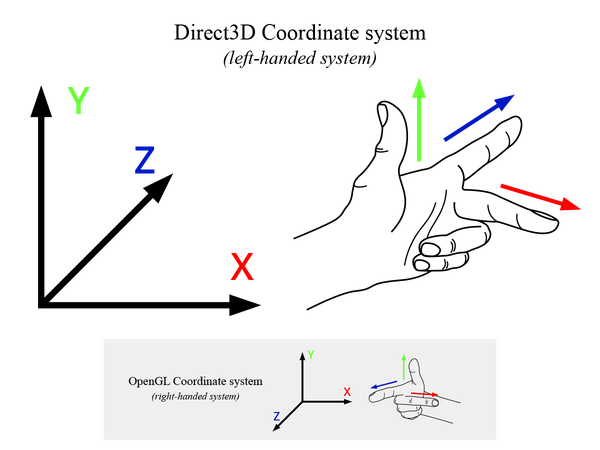
We define 3D geometry using vertex and index buffers. If it helps, you can imagine them as the “Connect the dots” puzzle from your childhood. The vertex buffer defines a list of points or vectors in space, using cartesian 3D coordinates – X, Y, and Z. Direct 3D uses a coordinate system, also known as the left-handed coordinate system (as opposed to OpenGL which uses right-handed, hence the inverted Z-axis):
| Direct3D uses left-handed coordinate system |
So, every single vertex in the vertex buffer is defining a position. Of course, that is not enough to display anything as a point does not define a volume all by itself.
Index buffer defines the order in which the vertices are to be connected, much like the numbers in the “Connect the dots.” The major difference here is that two index values do not directly define a line going between the two vertexes. Indices, depending on the selected primitive topology, define a primitive. In simpler terms, it is interpreted as what you asked it to be at the draw time. The most popular choice being – three indices define a triangle. And from a whole lot of triangles, you can construct just about anything you can imagine. There are other primitive types: lines, triangle strips, triangle-fans, etc. But again, the most used form is the triangle list, in which every triplet of indices defines a single triangle.
In the case of the sample cube, we have eight vertices in the vertex buffer. Those are used by the index buffer to create faces. When you define a surface by three indices, you end up with a face. Each side of the cube is composed of two faces – two pairs of triangles.
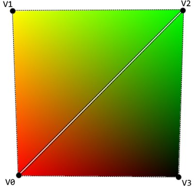
| Triangles composing two faces on a single side of the cube |
So, we end up with 6 sides, each having 2 faces (triangles) – a cube that is composed of 12 triangles. This, of course, translates into 36 indices in the index buffer.
There is a little catch in all of this though – we run into a phenomenon known as vertex winding order. Well, it’s not a phenomenon as much as an optimization technique. When we define a face, we are not telling it which way it is looking at, are we?
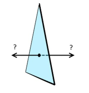
| Which side is the ‘face’ side in this triangle? |
Is the triangle visible from our side or from the back of the monitor? The easiest way would be to say, that it is visible either way – once a triangle is defined you should always see its face, regardless of the direction: it works that way in the real world – there are two sides for anything you are looking at. But with 3D graphics, you want to optimize as much as possible and not throw extra unnecessary work onto the processors. It does not make sense to process and draw triangles that cannot be seen. In case of a single triangle, you would be drawing two times even though the other side is hidden by the one you see at that instance. And in the case of a cube, you would never even see the faces that are on the inner walls of the cube. It might not sound like that big of a deal, and it isn’t… when we are talking about our little cube with only 6 polygons. But now imagine a model with millions of polygons, which if not back-face culled (that is what the process of eliminating unseen triangles is called) would, in turn, double the amount of data that needs to be processed.
That is where the vertex winding order comes into play. A face is considered to be facing the viewer when the vertices that compose it are in a clockwise order. So, we can see a triangle if the indices define the “connect the dots” order in a clockwise order. It does not matter which of the vertices within that triangle you start and end with, as long as the winding is done in a clockwise order.
Once again for comparison, since OpenGL is using right-handed coordinates, their winding order is also, by default, counter-clockwise.
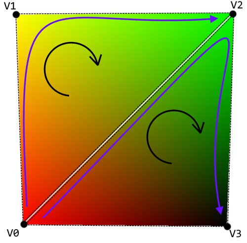
| Winding in Direct3D must be done in a clockwise order. The two triangles would then be defined as {v0, v1, v2} and {v0, v2, v3} |
The creation of the buffers is done inside the RenderableObject class in CreateVertexBuffer and CreateIndexBuffer methods. It’s pretty self-explanatory – you take the data, create the upload buffer and the usage buffer from the descriptors, and send the data over to the GPU. One thing to note here is that you must keep the buffer variables created with the CreateCommietedResource alive for as long as the data is being transferred over to the GPU. If you remove the descriptor too early, the object might not render at all.
DX::ThrowIfFailed(d3dDevice->CreateCommittedResource(
	&uploadHeapProperties,
	D3D12_HEAP_FLAG_NONE,
	&vertexBufferDesc,
	D3D12_RESOURCE_STATE_GENERIC_READ,
	nullptr,
	IID_PPV_ARGS(&m_vertexBufferUpload)));
3.4 Transformations
The original sample was already performing some transformations, but it was only doing it for one singular object. It is a whole different story when you need to draw more than one. And let’s be honest, you will most definitely want more than one object on the screen. Luckily, we already did some ground work with constant buffer initialization, so we only need to build upon that.
What exactly are Transformations, you ask? Well, in the simplest sense, a transformation is a way to alter an object so that it gets manipulated in space without modifying the underlying structure of the object itself. What does that mean exactly? Let me illustrate with an example.
Say we have a player avatar in our virtual world. You will most probably want it to be a non-stationary object. That means you want to have a way to move it around, rotate it to face the enemies etc. Transformations will help you with that.
Going even further, you have defined everything in your virtual world in 3D, right? You have your X, Y and Z axes, yes? But your monitor is not 3D. It’s pretty much a glorified two-dimensional piece of paper that can quickly change its contents. You only work with X and Y when dealing with monitor space. So how do you translate your 3D character to 2D space? You have guessed it right – transformations got you covered here too.
Transformations are defined by a 4×4 matrix. If you remember your math, a matrix is a two-dimensional array of numbers. The interesting thing with them is that they can do most of the usual mathematical operations. Another interesting thing is that if you multiply a matrix by a vector, that vector gets transformed by said matrix. Since transformations (matrices) work on per vertex (vector) base this turns out to be a match made in heaven.
3.4.1 Transformation Pipeline
Let’s take a quick look at the transformation pipeline.
The untransformed vertices within the geometry of the object inside a game must go through the strict transformation pipeline so that they correctly map to their final counterparts that could then be viewed on the monitor. The whole pipeline looks like this:
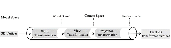
| Transformation pipeline |
The untransformed vertices that are part of your object, start in the Model Space. This means their positions are defined only in regard to each other.
Next, we take vertices that are in Model Space and apply World Transformations which changes their coordinates to World Space. This means that their positions are now defined in regard to vertices that are part of other objects within the world.
Then these vertices are once again transformed by the View Transformation. This aligns the object within the world to the Virtual Camera and flattens them for the 2D space.
Lastly the Projection Transformation gives the perspective to the vertices, so that the objects that are further away taper nicely, thus giving the illusion of depth. Now the vertices are in their final coordinates – the Screen Space.
Let’s quickly run through the most common transformations so we can make sense of all this.
3.4.1.1 Translation
To move an object to a specific position within the world we perform a Translation transformation. All you need to do to get the transformation matrix is call XMMatrixTranslation method and supply it with the end coordinates.
auto translation = XMMatrixTranslation(position.x, position.y, position.z);Translation is part of World Transformations.
3.4.1.2 Rotation
To rotate an object around any or all the axes we perform a Rotation transformation.
There are quite a few choices here depending on your personal taste or the way the rotation data is stored in your application. The transformation matrix can be retrieved by calling:
- any of the XMMatrixRotationX, XMMatrixRotationY or XMMatrixRotationZ and supplying it with the angle in radians to rotate around a specific axis.
auto rotation = XMMatrixRotationY(3.14f); - use the Roll-Pitch-Yaw notation with the XMMatrixRotationRollPitchYaw method and providing the appropriate values
auto rpyRotation = XMMatrixRotationRollPitchYaw(0, 0, 3.14f); - XMMatrixRotationAxis and supplying it with a vector which acts as an arbitrary axis around which the rotation will be performed by a provided amount.
auto axisRotation = XMMatrixRotationAxis(XMVECTOR(0, 1, 0), 3.14f); - XMMatrixRotationQuaternion and providing a quaternion value which describes a rotation.
auto quaternion = XMQuaternionRotationAxis({ 0, 1, 0 }, 3.14f); auto quatRotation = XMMatrixRotationQuaternion(quaternion);
All the above rotations will result in the same matrix that rotates an object around the Y axis by 180°.
Rotation is part of World Transformations.
3.4.1.3 Scale
To change the size of the object without adjusting its structural vector positions one can use Scaling transformation. The object can be enlarged or shrunken and not necessarily uniformly – meaning you can, if you want, only scale it only in Y axis to make it tall. Or use any other combination for that matter. Scale matrix is retrieved by calling XMMatrixScaling and supplying it with scale ratios for each axis. The ratio of 1.0 indicates no change, 2.0 would be doubling in size and 0.5 – shrunkenin half.
auto scale = XMMatrixScaling(2, 2, 2);Scaling is part of World Transformations.
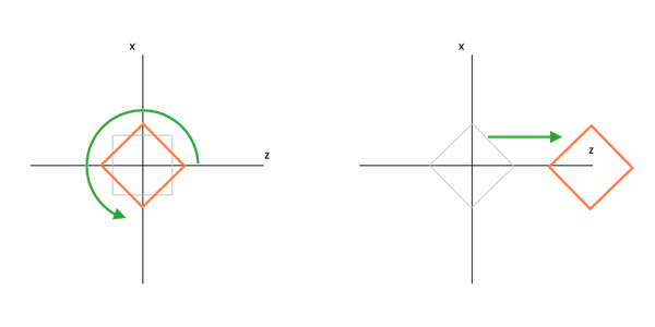
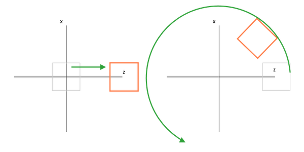
3.4.1.4 View
Since the virtual camera is a free moving object, it can end up in any place in the 3D world, rotated or even upside-down. This means that to properly render the object, we must first align the direction of the coordinate system to be in line with the virtual camera. The View Transformation does exactly that – it adjusts the 3D coordinates of all the vertices so that it is now aligned. The coordinates at this point enter the Camera Space (or View Space).
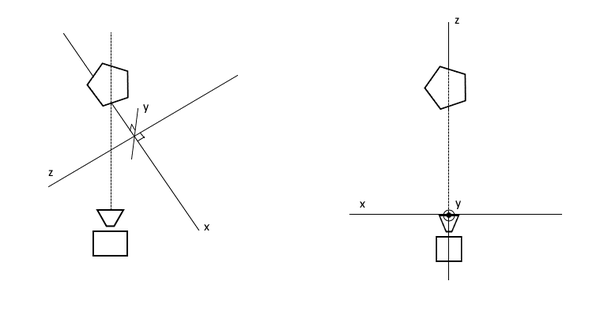
| Aligning axes to camera: left – unaligned, right – camera-space aligned |
To retrieve the view transformation matrix, we simply call XMMatrixLookAtLH method. Here LH stands for left-handed, so be careful not to confuse it with the very similar method ending with RH. The method should be supplied with EyePosition which is the location where the camera is, FocusPosition which is the point where the camera is looking at and the cameraUp which is the vector that describes which direction is considered “up”.
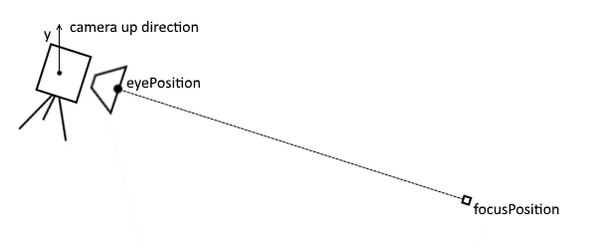
| XMMatrixLookAtLH parameter representation in relation to camera |
auto view = XMMatrixLookAtLH(XMVECTOR{ 0, 3, -10 }, XMVECTOR{ 0, 0, 0 }, XMVECTOR{ 0, 1, 0 });In this case we get a camera that is looking at the dead center of the world and is a bit away and elevated.
3.4.1.5 Projection
The Projection Transformation transforms the coordinates that are in View Space to their final coordinates in the Screen Space. By applying the projection transformation, we also obtain the illusion of depth with further objects starting to appear smaller in the final render. Or the lack of it, if using orthographic projection (via XMMatrixOrthographicLH method). This is mostly employed when doing 2D games that use sprites and don’t need any depth.
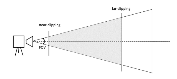
We would retrieve the projection transformation matrix by calling XMMatrixPerspectiveFovLH method. It should be provided with the fieldOfView value (pretty much all that the famous FOV slider in mainstream games do is just adjust this value), aspectRatio which is the dimension ratio of the rendering surface, nearClippingPlaneandafarClippingPlane which are the minimal and maximal distances at which the objects are still expected to be drawn.
View-plane clipping is done for performance reasons – the infamous Draw Distance limits the drawing of object that are far away and also prevents an object that is practically clipping the camera from covering the whole screen.
| XMMatrixPerspectiveFovLH parameter representation in relation to camera |
auto projection = XMMatrixPerspectiveFovLH(XM_PIDIV4, screenSize.Width / screenSize.Height, 1, 100);This code line would get us a projection matrix with a standard FOV angle, a ratio that is the ratio of the screen (since the back buffer is most of the time the dimensions of the screen), and objects will only get drawn if they are further than distance of 1 and less than 100 away from the camera.
3.4.1.6 Combining transformations
While reading through these last sections one question might have popped into your mind – what if I want to move the object AND give it a rotation too? Well the answer is pretty simple – multiplication. The only thing you need to do to combine one or more transformations expressed through matrices is to multiply them. The following line would result in a matrix that would transform vertices by rotating an object by its Y and X axis and would also move the object deeper into the screen:
auto rotateAndMove = XMMatrixRotationY(-3.14f / 2) * XMMatrixRotationX(0.001f) * XMMatrixTranslation(0, 0, 20);It is really simple except for one caveat – multiplication order. Unlike simple scalar values, the multiplication order with matrices do matter.
A result by rotating and then moving with transformations = matRotateY * matTranslate
| A result by moving before rotating with transformations = matTranslate * matRotateY |
This is nothing groundbreaking, but really helps to have it in mind to prevent unexpected behavior when applying transformations. The default multiplication order for transformations is:
auto transformations = matRotationX * matRotationY * matRotationZ * matScale * matTranslate * matView * matProjection;3.4.2 Camera
Since there is quite a bit of functionality regarding virtual camera it would be handy to have all the related functionality encapsulated in a class. For this purpose, we have a Camera class in VoiceMaze\CommonElements. The functionality from Sample3DSceneRenderer related to dealing with perspective and view transformations were moved to this new class.
The class can be used to get view and projection matrices, scissor rectangle, and the camera view vector that will come in handy when dealing with effects in later chapters.
3.4.3 Transformation data
Among other things the newly added RenderableObject base class has the responsibility of maintaining the information about its spatial positioning, scale and rotations. When rendering, this data is converted to the appropriate transformations which are then passed to an appropriate constant buffer.
3.4.4 Constant buffers
In its essence, the job of a Constant Buffer is to carry the information from the main application to the shader subroutine.
You must first declare and initialize a descriptor. For this purpose, we have a BufferDescriptor class. It creates a CBV in the descriptor heap, also considering the frame buffering amount to version the constant buffer data for shaders.
A popular approach is to separate the constant buffers into at least two categories. We will have a buffer that changes only once every frame – the camera-based data, lighting data, etc. We will call this one PerFrameConstantBuffer. And then we will have a buffer that changes many times per frame – it will be different for every object that is rendered: a single object has different transformations, maybe some additional lighting data, etc. This will be called PerObjectConstantBuffer. This is done for performance reasons, because by updating only the buffers that are actually changing you would be saving on memory bandwidth. Sometimes you might encounter static constant buffers. These are often run time defined constants for shader that rarely, if ever, change during the operation of the application (like, f.e. screen size).
The data structure resides in BaseClasses\ShaderStructures.h. It looks something like this:
struct PerObjectConstantBuffer
{
	DirectX::XMFLOAT4X4 Transformations;
};
There are two camps when passing transformation data to the shader: some people like to pass all transformations separately – world, view and projection and then perform the multiplication in the shader itself. I like to pass the transformations already premultiplied to save doing the same operation for every single vertex in the object.
To update the descriptor itself, we will use BufferDescriptor’s UpdateBuffer method and it will copy the data over. For the shader and in turn – GPU to access.
3.5 Game Loop
If you would look at the contents of the App.cpp file, you would come across its Run method. Within it we have a structure that is called a Game Loop. Inside we have a while loop that runs for as long as the application window is not closed.
// This method is called after the window becomes active.
void App::Run()
{
	while (!m_windowClosed)
	{
		if (m_windowVisible)
		{
			CoreWindow::GetForCurrentThread()->Dispatcher->ProcessEvents(CoreProcessEventsOption::ProcessAllIfPresent);

			auto commandQueue = GetDeviceResources()->GetCommandQueue();
			PIXBeginEvent(commandQueue, 0, L"Update");
			{
				m_main->Update();
			}
			PIXEndEvent(commandQueue);

			PIXBeginEvent(commandQueue, 0, L"Render");
			{
				if (m_main->Render())
				{
					GetDeviceResources()->Present();
				}
			}
			PIXEndEvent(commandQueue);
		}
		else
		{
			CoreWindow::GetForCurrentThread()->Dispatcher->ProcessEvents(CoreProcessEventsOption::ProcessOneAndAllPending);
		}
	}
}
What it does is: it processes all the events that arrive to the window, like close, minimize events and so on. This part used to be known as the Message Pump. If the window is visible it performs two critical parts that form the basis for all games currently in existence: Update and Render methods. After that, the rendered data is presented on screen and the same process starts again: events, update, render. Rinse and repeat.
This happens up to 60 or even 120 times a second. In theory you could go even further provided your system is powerful enough and the rendered scenes are not overly complex. Going over 120 FPS is pointless though as the visual perception of a human eye is limited. Remember – even movies are only played in 24 FPS. More frames result in a smoother looking motion: 60 FPS seems to be the sweet spot, 120 often has a panacea effect and anything above that is pretty much just a wear on the hardware and a waste of electricity.
Update method updates the state of the game world. You can imagine it as the action phase – projectiles are moved, player avatar reacts to input, camera adapts to the best possible position, physics are applied, etc. Usually a small timeframe – time delta is used which defines how much time passed since the last update and the objects can be manipulated according to that – just like with physics formulas (and those are actually often reused in the virtual world) in the real world.
Render method, on the other hand, is (or at the very least should be) like a still photography – all the objects that were previously positioned, are now being exposed to the camera, their vertices transformed from 3D to 2D, shaders run, various effects are applied and, in this implementation, if it completes successfully, the resulting contents are presented to the player on the monitor.
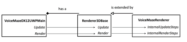
| This is how the game loop performing classes are related in VoiceMaze structure |
In Voice Maze, we have a VoiceMazeDX12UWPMain class that has a StepTimer instance, so it can retrieve the time delta. It also has a reference to a scene renderer, namely, Renderer3DBase’s concrete implementation – VoiceMazeRenderer. When an Update is called on VoiceMazeDX12UWPMain from App.cppgame loop, it subsequently calls Update on the Renderer3DBase and provides a reference to the timer. Inside it performs a call to the concrete implementation’s InternalUpdateSteps method which does the actual, application-specific update, also supplying it with the time delta value.
Render wise, it goes similarly: when a Render is called on VoiceMazeDX12UWPMain from App.cpp, it calls Render on the Renderer3DBase. Within this method a lot of common basic rendering setup is performed and after that the InternalRenderSteps is called which performs application specific rendering commands.
3.6 Content Manager
For the sake of completion, I will do a short detour and say a few words about ContentManager class.
The purpose of the content manager in our little framework is that we would have a central place through which we would be loading content – textures, meshes, sounds (not in this project) and so on. It helps to have a common way of loading those files so that you don’t litter your codebase with loading calls in every place this functionality is needed. Also, in case you happen to use the same resource in multiple places, you could reuse the already loaded instance (that the content manager saves a reference to) and save on some processor cycles and memory. And, last but not least, once application decides to free the resources you will have one and only one place where you can do exactly that.
The content manager is initialized inside the GameBase class which is extended by VoiceMazeDX12UWPMain.
3.7 Shaders
Shaders. You probably have heard this word over and over whenever computer graphics related topic comes along. And there is a reason for that – shaders are a big thing. So, what exactly are they then?
A shader is a subroutine in your application that runs on the GPU and allows you to control the programmable GPU rendering pipeline. Simply said, they run every time you perform a render operation and they are the final frontier that do the final vertex transformations, rasterizations, polygon coloring ant post processing effects. The result that comes out is displayed on the screen afterwards.
The biggest thing about a shader is that their operations are run in parallel. This is where the greatest performance boost happens. Imagine if calculation for every pixel on your screen is calculated on its own dedicated CUDA core in the GPU (not entirely true, but helps to paint the overall picture), as opposed to doing one by one in a linear fashion. Mythbusters actually did a really nice job explaining this difference. Just google “mythbusters cpu vs gpu”.
Current day and age graphical pipeline is extremely configurable and programmable. In turn there are quite a few different shader stages, like Hull shader, Domain shader, Compute shader, etc. We will only bother ourselves with two main ones: Vertex Shader and Pixel Shader (in other circles known as the Fragment Shader).
Vertex Shader runs on every vertex that you render. Here you would typically perform transformations, do lighting calculations and pass on coloring data to further stages. The shader code is in Content\SampleVertexShader.hlsl file.
Pixel Shader, as a rule of thumb, runs for every pixel that is going to be rendered. Though to be more specific, it runs for each pixel that is covered by a primitive. And there are many other factors that might interfere with this notion too – like multiple primitives with alpha transparency covering the same pixel, so, in turn running multiple times, etc. Considering this, I like the name of “Fragment Shader” more, from the standpoint of the meaning of this stage, but for this article we will keep calling it a “Pixel Shader” as DirectX refers to it with this name. Pixel shaders calculate the final color of the pixel, taking into account material colors, lighting, textures, etc. You can even go commando mode here and implement per-pixel lighting calculations and post-processing effects in a Pixel Shader. The shader code is in Content\SamplePixelShader.hlsl file.
The shaders themselves are written in HLSL (High-Level Shading language) or its similar cousin GLSL (OpenGL Shading Language). Nice thing is that both are very similar, and if you find a particular code on the internet you like, you can port one to the other quite easily.
When working with shaders in Visual Studio I would highly recommend downloading HLSL Tools for Visual Studio. It provides you with highlighting, syntax checking and makes the coding a much more enjoyable experience.
To shed light on the subject, let’s run through a rendering sample and get our heads around what is actually happening in one Rendering pass. Please note, that the code is a bit different in the final version of the code as there will be quite a few new parts added to this and the code is refactored to make it more self-sufficient, but this is much clearer and straight to the point.
bool VoiceMazeRenderer::InternalRenderSteps()
{
	// update camera
	XMFLOAT4X4 viewProjection;
	XMFLOAT4X4 orientation = m_deviceResources->GetOrientationTransform3D();
	auto viewProjectionMatrix = m_camera->CalculateViewMat() * m_camera->CalculateProjectionMat(orientation);
	XMStoreFloat4x4(&viewProjection, viewProjectionMatrix);

	// Record drawing commands.
	D3D12_CPU_DESCRIPTOR_HANDLE renderTargetView = m_deviceResources->GetRenderTargetView();
	D3D12_CPU_DESCRIPTOR_HANDLE depthStencilView = m_deviceResources->GetDepthStencilView();
	m_commandList->ClearRenderTargetView(renderTargetView, DirectX::Colors::CornflowerBlue, 0, nullptr);
	m_commandList->ClearDepthStencilView(depthStencilView, D3D12_CLEAR_FLAG_DEPTH, 1.0f, 0, 0, nullptr);

	m_commandList->OMSetRenderTargets(1, &renderTargetView, false, &depthStencilView);

	{
		auto frameIndex = m_deviceResources->GetCurrentFrameIndex();

		m_mazeElement->Render(m_commandList, frameIndex, viewProjection);
		m_mazeElement2->Render(m_commandList, frameIndex, viewProjection);
		m_mazeElement3->Render(m_commandList, frameIndex, viewProjection);
	}


	return true;
}
The first few lines in the VoiceMazeRenderer implementation should be familiar to you from the Camera section. It just takes the various transformations and combines them into view * projection matrix. XMStoreFloat just copies the matrix into a FLOAT4X4 structure which is a lot easier to pass around. After that we get handles to two important entities for the drawing – the renderTargetView – which is our drawing surface and the depthStencilView which is our depth buffer. Next, we wipe away any data that is currently on the draw surface with the ClearRenderTargetView command and also while we are at it we give it a familiar uniform blue color. We also perform a similar operation on the depth stencil. Then we indicate that these two buffers will be used in the drawing operations with the OMSetRenderTargets command.
Now we come to the drawing of individual objects. This happens in the Render method of the RenderableObject class:
void RenderableObject::Render(const Microsoft::WRL::ComPtr &commandList, UINT8 frameIndex, XMFLOAT4X4 transformations)
{
	// Update constant buffers
	ID3D12DescriptorHeap* ppHeaps[] = { m_cbvHeap.Get() };
	commandList->SetDescriptorHeaps(_countof(ppHeaps), ppHeaps);

	// Bind the current frame's constant buffer to the pipeline.
	CD3DX12_GPU_DESCRIPTOR_HANDLE gpuHandle(m_cbvHeap->GetGPUDescriptorHandleForHeapStart(), frameIndex, m_cbvDescriptorSize);
	commandList->SetGraphicsRootDescriptorTable(0, gpuHandle);

	auto worldTransform = GetTransformations();
	auto transformationsMatrix = worldTransform * XMLoadFloat4x4(&transformations);

	XMStoreFloat4x4(&m_constantBufferData.transformations, XMMatrixTranspose(transformationsMatrix));
	// Update the constant buffer resource.
	UINT8* destination = m_mappedConstantBuffer + (frameIndex * c_alignedConstantBufferSize);
	memcpy(destination, &m_constantBufferData, sizeof(m_constantBufferData));

	commandList->IASetPrimitiveTopology(D3D_PRIMITIVE_TOPOLOGY_TRIANGLELIST);
	commandList->IASetVertexBuffers(0, 1, &m_vertexBufferView);
	commandList->IASetIndexBuffer(&m_indexBufferView);
	commandList->DrawIndexedInstanced(m_indexCount, 1, 0, 0, 0);
}
We start by getting the address of the constant buffer of this particular renderable object and indicating that this constant buffer will be used for the following operations. After we finish up with this initialization we move onto the fun part that is getting the transformations of this object and copying those over onto the constant buffer struct. Since constant buffers must be stored at 256 byte offsets from the resource heap beginning before the final memcpy, we align the addresses to do exactly that.
The last few operations are actual drawing of the primitives. We indicate the most common topology that our current render object uses – a Triangle list. Then we indicate the GPU which vertex buffer and index buffer will be used for this operation with IASetVertexBuffers and IASetIndexBuffer commands respectively. Lastly, we ask the GPU to draw the primitive by using the data we just configured by calling the DrawIndexedInstanced method.
Now, once this next line of code in Renderer3DBase is executed, all the provided data will be picked up and processed by the shader code:
m_deviceResources->GetCommandQueue()->ExecuteCommandLists(_countof(ppCommandLists), ppCommandLists);Template default Vertex Shader code:
// A constant buffer that stores the three basic column-major matrices for composing geometry combined in one.
cbuffer ModelViewProjectionConstantBuffer : register(b0)
{
	matrix transformations;
};

// Per-vertex data used as input to the vertex shader.
struct VertexShaderInput
{
	float4 pos : POSITION;
	float4 color : COLOR0;
};

// Per-pixel color data passed through the pixel shader.
struct VertexShaderOutput
{
	float4 pos : SV_POSITION;
	float4 color : COLOR0;
};

// Simple shader to do vertex processing on the GPU.
VertexShaderOutput main(VertexShaderInput input)
{
	VertexShaderOutput output;

	output.pos = mul(input.pos, transformations);
	output.color = input.color;

	return output;
}
So, the Vertex shader will be picking up the vertex data and running the main method once for every one of them. The constant buffer data arrives into the transformations variable and position & color value of each of the vertices will be in the input variable that is of the conveniently placed VerexShaderInputtype. In the main method we just want to fill in the output variable which will be the input for the Pixel shader. We do this by transforming the vertex positions through all the hoops of the transformations straight to the screen space. The color value just gets passed through.
Template default Pixel Shader code:
// Per-pixel color data passed through the pixel shader.
struct PixelShaderInput
{
	float4 pos : SV_POSITION;
	float3 color : COLOR0;
};

// A pass-through function for the (interpolated) color data.
float4 main(PixelShaderInput input) : SV_TARGET
{
	return float4(input.color, 1.0f);
}
The job of the Pixel shader is just to output the final pixel color – so we get the information that was sent in by the Vertex shader and just return that. The intermediate values between two vertices are all interpolated by the GPU for us.
The easiest way to get to know the shaders is to try and construct a few of them. To learn more about shaders I strongly suggest taking some shader centered tutorial and trying it out at the shadertoy.com.
So, after all this we get this onto the screen:
| These are all 1x1x1 cubes that have had their shape, position and rotation changed by the transformations |
4. ADDITIONAL ESSENTIAL 3D ELEMENTS
4.1 Texturing
First off, we will be adding textures. Textures add more life to rendered scene as you can only go so far with just color-coded vertices as was in the template.
Texture is an image that is applied to the surface of a shape. Every vertex in a ploygon is assigned a texture coordinate (which is also known as a UV coordinate). So, to build one side of a box you would have 4 vertices that contain UV coordinates of the assigned texture. You’d arrange those vertices in a certain order to produce two triangles that make the final face of a box.
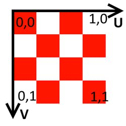
UV coordinates are a bit special. Since the image that is loaded in memory is in screen coordinates (i.e. point [0,0] is top-left), UV coordinates start in the top left and range from 0 to 1 (floating point values). Please see the image below for illustration. OpenGL, as per usual, has the V coordinate axis inverted.
| UV coordinates |
Now to load the textures into the memory, apply and render them.
The image loading itself is done via ContentManager. By calling its Load method and supplying it with the relative path to the image, we receive a Textureobject, which encapsulates the creation of the descriptor heap and which we pass to the objects that need it. The image loading and conversion happens inside the ImageLoader class. You can find the URL to the page describing the loading procedure in detail in the Links section.
To accommodate these changes, we will make changes to the vertex structure, constant buffer and the shaders. First off – a new vertex structure:
static D3D12_INPUT_ELEMENT_DESC layout[] =
{
	{ "POSITION", 0, DXGI_FORMAT_R32G32B32_FLOAT, 0, D3D12_APPEND_ALIGNED_ELEMENT, D3D12_INPUT_CLASSIFICATION_PER_VERTEX_DATA, 0 },
	{ "TEXCOORD", 0, DXGI_FORMAT_R32G32_FLOAT, 0, D3D12_APPEND_ALIGNED_ELEMENT, D3D12_INPUT_CLASSIFICATION_PER_VERTEX_DATA, 0 }
};
The Color component was removed in place of a texture coordinate – a 2D vector. Now each vertex will carry with it the UV coordinates that will map that corner to a position within the texture. A complication that is brought about by it is that we will not be able to make do with only 8 vertices. Once we move to texturing a cube, each vertex might need to describe 3 different UV coordinates for each of the faces while the position is shared. It was fine for a color cube, as we only defined a color and it was then gradually changed to another. If you try and use the same approach for the textures, you might find that some of the faces get garbled, since we are using a full texture that stretches full UV values over one face. This increase in number of vertices means that we will now have duplicate data (actually, 3 times as much, as every shared corner will now have a set of 3 vertices). The good news is that we would need to do this for the lighting chapter anyway. So, now the definition of the cube would look something like:
// Cube vertices. Each vertex has a position and a texture coordinate.
std::vector cubeVertices =
{
	//top
	{ XMFLOAT3(-0.5f,	0.5f,	-0.5f),		XMFLOAT2(1.0f, 1.0f) },
	{ XMFLOAT3(-0.5f,	0.5f,	 0.5f),		XMFLOAT2(1.0f, 0.0f) },
	{ XMFLOAT3( 0.5f ,	0.5f,	 0.5f),		XMFLOAT2(0.0f, 0.0f) },
	{ XMFLOAT3( 0.5f ,	0.5f,	-0.5f),		XMFLOAT2(0.0f, 1.0f) },

	//left
	{ XMFLOAT3(-0.5f,	-0.5f,	 0.5f),		XMFLOAT2(1.0f, 1.0f) },
	{ XMFLOAT3(-0.5f,	 0.5f,	 0.5f),		XMFLOAT2(1.0f, 0.0f) },
	{ XMFLOAT3(-0.5f,	 0.5f,	-0.5f),		XMFLOAT2(0.0f, 0.0f) },
	{ XMFLOAT3(-0.5f,	-0.5f,	-0.5f),		XMFLOAT2(0.0f, 1.0f) },

	//back
	{ XMFLOAT3( 0.5f,	-0.5f,	 0.5f),		XMFLOAT2(1.0f, 1.0f) },
	{ XMFLOAT3( 0.5f,	 0.5f,	 0.5f),		XMFLOAT2(1.0f, 0.0f) },
	{ XMFLOAT3(-0.5f,	 0.5f,	 0.5f),		XMFLOAT2(0.0f, 0.0f) },
	{ XMFLOAT3(-0.5f,	-0.5f,	 0.5f),		XMFLOAT2(0.0f, 1.0f) },

	//right
	{ XMFLOAT3( 0.5f,	-0.5f,	-0.5f),		XMFLOAT2(1.0f, 1.0f) },
	{ XMFLOAT3( 0.5f,	 0.5f,	-0.5f),		XMFLOAT2(1.0f, 0.0f) },
	{ XMFLOAT3( 0.5f,	 0.5f,	 0.5f),		XMFLOAT2(0.0f, 0.0f) },
	{ XMFLOAT3( 0.5f,	-0.5f,	 0.5f),		XMFLOAT2(0.0f, 1.0f) },

	//front
	{ XMFLOAT3(-0.5f,	-0.5f,	-0.5f),		XMFLOAT2(1.0f, 1.0f) },
	{ XMFLOAT3(-0.5f,	 0.5f,	-0.5f),		XMFLOAT2(1.0f, 0.0f) },
	{ XMFLOAT3( 0.5f,	 0.5f,	-0.5f),		XMFLOAT2(0.0f, 0.0f) },
	{ XMFLOAT3( 0.5f,	-0.5f,	-0.5f),		XMFLOAT2(0.0f, 1.0f) },

	//bottom
	{ XMFLOAT3( 0.5f,	-0.5f,	-0.5f),		XMFLOAT2(1.0f, 1.0f) },
	{ XMFLOAT3( 0.5f,	-0.5f,	 0.5f),		XMFLOAT2(1.0f, 0.0f) },
	{ XMFLOAT3(-0.5f,	-0.5f,	 0.5f),		XMFLOAT2(0.0f, 0.0f) },
	{ XMFLOAT3(-0.5f,	-0.5f,	-0.5f),		XMFLOAT2(0.0f, 1.0f) },
};
Where the first parameter indicates the vertex position and second – the UV coordinates. As you can see we have 24 value sets instead of previous 8.
Now we will need to indicate which texture to use via constant buffer. A RenderableObject now has a member that stores the texture – m_texture. If you remember we created 3 slots in the initialization, so now we will set the root parameter with the index 2 to point to this texture so that it could be used by the pixel shader.
{
	// Update texture
	ID3D12DescriptorHeap* ppHeaps2[] = { m_texture->GetTextureDescriptor() };
	commandList->SetDescriptorHeaps(_countof(ppHeaps2), ppHeaps2);

	commandList->SetGraphicsRootDescriptorTable(2, m_texture->GetTextureDescriptor()->GetGPUDescriptorHandleForHeapStart());
}
The shaders get a facelift too.
// A constant buffer that stores the three basic column-major matrices for composing geometry pre-multiplied.
cbuffer PerObjectConstantBuffer : register(b0)
{
	matrix transformations;
};

cbuffer PerFrameConstantBuffer : register(b1)
{
};

// Per-vertex data used as input to the vertex shader.
struct VertexShaderInput
{
    float4 pos : POSITION;
    float2 texCoord : TEXCOORD;
};

// Per-pixel color data passed through to the pixel shader.
struct VertexShaderOutput
{
	float4 pos : SV_POSITION;
    float2 texCoord : TEXCOORD;
};

// Simple shader to do vertex processing on the GPU.
VertexShaderOutput main(VertexShaderInput input)
{
    VertexShaderOutput output;

    output.pos = mul(input.pos, transformations);
    output.texCoord = input.texCoord;

    return output;
}
As you can see, the vertex shader now has a new texCoord input parameter, which mimics the new incoming texture coordinate data. This information is just passed through to the Pixel Shader (and it will be interpolated by the GPU for the points in the middle, to get the in-between texture values for each fragment).
// Per-pixel color data passed through the pixel shader.
Texture2D tex : register(t0);
SamplerState samplerState : register(s0);

struct PixelShaderInput
{
	float4 pos : SV_POSITION;
    float2 texCoord : TEXCOORD;
};

// Pixel shader processing.
float4 main(PixelShaderInput input) : SV_TARGET
{
    return tex.Sample(samplerState, input.texCoord);
}
The Pixel Shader accepts the texCoord parameter and feeds it to the texture sampler – the way the shaders access textures – which in turn spews out a color to be used.
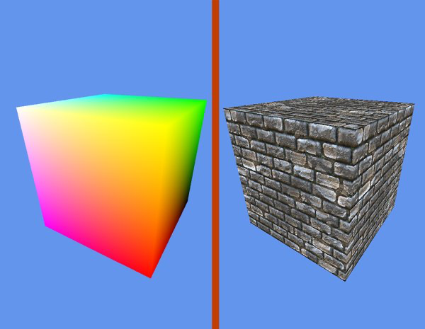
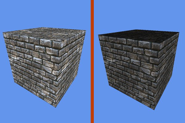
| When we run the modified code, we get the textured cube on the right |
4.2 Basic Lighting
Next is the lighting. When we talk about lighting in 3D graphics, we talk about normals. A normal is a vector that is perpendicular to the face that the light falls onto. As the surface tilts farther away from the angle of the light, the normal vector becomes more exposed to the light, or in mathematical terms – the light direction vector has a bigger projection onto the surface normal. Direct3D compares the angle of the normal to the angle of the light to determine how brightly lit the surface should be. The surface is brighter the closer these two angles are to each other.
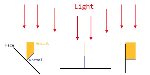
| The amount of light that hits the surface is calculated with the aid of surface normals |
This physical phenomenon can easily be replicated at home – just take a piece of white paper and fold it in half. If you fully unfold it, it will be all the same color. Now if you fold it halfway, so that it makes an ‘L’ shape, observe the two points that are really close to the crease – one on the bottom part and one facing upwards: even though they are the same material that is the same color, they appear to be different because of the lighting angle. We want the same behavior in our rendering process.
Lighting rendering is often composed of three separate lighting stages: Ambient, Diffuse and Specular.
Ambient light is the light that could be associated with the scattered daylight. As the light shines onto a surface it is reflected to the other surfaces, that is reflected again to other surfaces and so on. The ambient lighting allows us to simulate this indirect lighting without doing absurd levels of reflecting light calculations. This way even the dark parts of the scene can be made somewhat visible.
Diffuse light is the directional light that illuminates the surface. The full normal calculations are performed for this step, so the object reacts naturally to the light as it is being rotated and moved around.
Specular light is the highlights on the surface which are the result of a glossy surface reflecting the light directly into the viewers eye. They are usually small, high intensity patches of very bright color that appear on the surface of the object.
To prepare for all this, we update the input structure once more.
static const D3D12_INPUT_ELEMENT_DESC inputLayout[] =
{
	{ "POSITION", 0, DXGI_FORMAT_R32G32B32_FLOAT, 0, D3D12_APPEND_ALIGNED_ELEMENT, D3D12_INPUT_CLASSIFICATION_PER_VERTEX_DATA, 0 },
	{ "NORMAL", 0, DXGI_FORMAT_R32G32B32_FLOAT, 0, D3D12_APPEND_ALIGNED_ELEMENT, D3D12_INPUT_CLASSIFICATION_PER_VERTEX_DATA, 0 },
	{ "TEXCOORD", 0, DXGI_FORMAT_R32G32_FLOAT, 0, D3D12_APPEND_ALIGNED_ELEMENT, D3D12_INPUT_CLASSIFICATION_PER_VERTEX_DATA, 0 }
};
In addition to the two parameters you are already familiar with, we add an additional one – a 3D vector that represents the surface normal. Since we already bumped up the vertex count in the texturing chapter, we will only be adding one more parameter in the initialization of each vertex.
One more note on the tripling of the vertex data for the lighting. Even though there was a possibility to manage the texturing with only 8 vertices by carefully planning the texture input image layout and the UV textures, there is no way we could pull off the same magic here. As all the faces on all the corners are perpendicular to each other – their normals are also perpendicular to each other. So, we will need 3 separate component vertices to get the desired results.
// Cube vertices. Each vertex has a position, a normal and a texcoord.
std::vector cubeVertices =
{
	//top
	{ XMFLOAT3(-0.5f, 0.5f, -0.5f),		XMFLOAT3(0, 1, 0),	XMFLOAT2(1.0f, 1.0f) },
	{ XMFLOAT3(-0.5f, 0.5f,  0.5f),		XMFLOAT3(0, 1, 0),	XMFLOAT2(1.0f, 0.0f) },
	{ XMFLOAT3(0.5f, 0.5f,  0.5f),		XMFLOAT3(0, 1, 0),	XMFLOAT2(0.0f, 0.0f) },
	{ XMFLOAT3(0.5f, 0.5f, -0.5f),		XMFLOAT3(0, 1, 0),	XMFLOAT2(0.0f, 1.0f) },

	//left
	{ XMFLOAT3(-0.5f, -0.5f,  0.5f),	XMFLOAT3(-1, 0, 0),	XMFLOAT2(1.0f, 1.0f) },
	{ XMFLOAT3(-0.5f,  0.5f,  0.5f),	XMFLOAT3(-1, 0, 0),	XMFLOAT2(1.0f, 0.0f) },
	{ XMFLOAT3(-0.5f,  0.5f, -0.5f),	XMFLOAT3(-1, 0, 0),	XMFLOAT2(0.0f, 0.0f) },
	{ XMFLOAT3(-0.5f, -0.5f, -0.5f),	XMFLOAT3(-1, 0, 0),	XMFLOAT2(0.0f, 1.0f) },

	//back
	{ XMFLOAT3(0.5f, -0.5f, 0.5f),		XMFLOAT3(0, 0, 1),	XMFLOAT2(1.0f, 1.0f) },
	{ XMFLOAT3(0.5f,  0.5f, 0.5f),		XMFLOAT3(0, 0, 1),	XMFLOAT2(1.0f, 0.0f) },
	{ XMFLOAT3(-0.5f, 0.5f, 0.5f),		XMFLOAT3(0, 0, 1),	XMFLOAT2(0.0f, 0.0f) },
	{ XMFLOAT3(-0.5f,-0.5f, 0.5f),		XMFLOAT3(0, 0, 1),	XMFLOAT2(0.0f, 1.0f) },

	//right
	{ XMFLOAT3(0.5f, -0.5f, -0.5f),		XMFLOAT3(1, 0, 0),	XMFLOAT2(1.0f, 1.0f) },
	{ XMFLOAT3(0.5f,  0.5f, -0.5f),		XMFLOAT3(1, 0, 0),	XMFLOAT2(1.0f, 0.0f) },
	{ XMFLOAT3(0.5f,  0.5f,  0.5f),		XMFLOAT3(1, 0, 0),	XMFLOAT2(0.0f, 0.0f) },
	{ XMFLOAT3(0.5f, -0.5f,  0.5f),		XMFLOAT3(1, 0, 0),	XMFLOAT2(0.0f, 1.0f) },

	//front
	{ XMFLOAT3(-0.5f, -0.5f, -0.5f),	XMFLOAT3(0, 0, -1),	XMFLOAT2(1.0f, 1.0f) },
	{ XMFLOAT3(-0.5f,  0.5f, -0.5f),	XMFLOAT3(0, 0, -1),	XMFLOAT2(1.0f, 0.0f) },
	{ XMFLOAT3(0.5f,   0.5f, -0.5f),	XMFLOAT3(0, 0, -1),	XMFLOAT2(0.0f, 0.0f) },
	{ XMFLOAT3(0.5f,  -0.5f, -0.5f),	XMFLOAT3(0, 0, -1),	XMFLOAT2(0.0f, 1.0f) },

	//bottom
	{ XMFLOAT3(0.5f,  -0.5f, -0.5f),	XMFLOAT3(0, -1, 0),	XMFLOAT2(1.0f, 1.0f) },
	{ XMFLOAT3(0.5f,  -0.5f,  0.5f),	XMFLOAT3(0, -1, 0),	XMFLOAT2(1.0f, 0.0f) },
	{ XMFLOAT3(-0.5f, -0.5f,  0.5f),	XMFLOAT3(0, -1, 0),	XMFLOAT2(0.0f, 0.0f) },
	{ XMFLOAT3(-0.5f, -0.5f, -0.5f),	XMFLOAT3(0, -1, 0),	XMFLOAT2(0.0f, 1.0f) },
};
We will also need to send in some additional data via constant buffers. Per-object buffers will have two additional parameters:
WorldInverseTranspose which will store the inverse of the world matrix. We need it so that we would be able to transform normals for the lighting calculations. The actual data is retrieved by calling XMMatrixInverse with the world transformations matrix.
PremultipliedViewVector which is the vector that indicates the direction the camera or the ‘eye’ is looking in. Since specular lighting highlights depends on where the viewer is, this data will come in handy. We pre-multiply it by the world matrix so that it saves a few cycles in the shader code.
auto viewVector = XMLoadFloat4(&camera->GetViewVector());
auto premultipliedViewVector = XMVector4Normalize(XMVector4Transform(XMVector4Normalize(viewVector), XMMatrixTranspose(worldTransform)));

auto perObjectData = PerObjectConstantBuffer();
XMStoreFloat4x4(&perObjectData.Transformations, XMMatrixTranspose(transformationsMatrix));
XMStoreFloat4x4(&perObjectData.WorldInverseTranspose, XMMatrixInverse(nullptr, worldTransform));
XMStoreFloat4(&perObjectData.PremultipliedViewVector, premultipliedViewVector);
The per-frame constant buffer will get a ton of new variables, though to be fair, it didn’t have any to begin with.
DiffuseLightDirection – the vector indicating the direction the light will be shining in;
DiffuseLightColor – the color that the diffuse light will tint the objects in;
AmbientLightColor – same as above, just with ambient lighting;
SpecularLightColor – the color of specular highlights. This is often set to a near-white color, as this is supposed to be the light that is reflected to your eyes from a shiny surface;
DiffuseLightIntensity – the factor of the diffuse color brightness;
AmbientLightIntensity – the factor for the brightness of ambient light;
SpecularLightIntensity – indicates how much light will be reflected by the surface;
Shininess – indicates how shiny the surface is. The lower values will produce broad highlights and the higher it goes the sharper and pin-pointed the highlights become.
Most of the parameters are pre-set and do not change while the game is running (although they very well could).
struct PerFrameConstantBuffer
{
	DirectX::XMFLOAT4 DiffuseLightDirection;
	DirectX::XMFLOAT4 DiffuseLightColor;

	DirectX::XMFLOAT4 AmbientLightColor = DirectX::XMFLOAT4(1, 1, 1, 1);
	DirectX::XMFLOAT4 SpecularLightColor = DirectX::XMFLOAT4(1, 1, 1, 1);

	float DiffuseLightIntensity = 1.0;
	float AmbientLightIntensity = 0.1;
	float Shininess = 200;
	float SpecularLightIntensity = 1.0;
};
The rest of the data, related to the diffuse light comes from the LightSource object and is set by VoiceMazeRenderer in every render operation
PerFrameConstantBuffer perFrameData = PerFrameConstantBuffer();
perFrameData.DiffuseLightColor = m_lightSource.GetColor();
perFrameData.DiffuseLightDirection = m_lightSource.GetDirection();

m_perFrameCB.UpdateBuffer(perFrameData, frameIndex, 1, m_commandList);
The only part that’s left is to update the shaders to include the lighting computation logic.
// A constant buffer that stores the three basic column-major matrices for composing geometry pre-multiplied
cbuffer PerObjectConstantBuffer : register(b0)
{
	matrix Transformations;
    matrix WorldInverseTranspose;
    float4 PremultipliedViewVector;
};

cbuffer PerFrameConstantBuffer : register(b1)
{
    float4 DiffuseLightDirection;

    float4 DiffuseLightColor;
    float4 AmbientLightColor;
    float4 SpecularLightColor;

    float DiffuseLightIntensity;
    float AmbientLightIntensity;
    float Shininess;
    float SpecularLightIntensity;
};

// Per-vertex data used as input to the vertex shader.
struct VertexShaderInput
{
    float4 Position : POSITION;
    float4 Normal: NORMAL;
    float2 TexCoord : TEXCOORD;
};

// Per-pixel data that is passed through to the pixel shader.
struct VertexShaderOutput
{
    float4 Position : SV_POSITION;
    float4 Normal : NORMAL;
    float4 Color : COLOR;
    float4 PremultipliedViewVector : NORMAL1;
    float2 TexCoord : TEXCOORD;
};

// Vertex processing and preliminary vertex dependent lighting calculations.
VertexShaderOutput main(VertexShaderInput input)
{
    VertexShaderOutput output;

    output.Position = mul(input.Position, Transformations);

    float4 normal = normalize(mul(input.Normal, WorldInverseTranspose));
    float lightIntensity = dot(normal, DiffuseLightDirection);
    output.Color = saturate(DiffuseLightColor * DiffuseLightIntensity * lightIntensity);

    output.Normal = normal;
    output.TexCoord = input.TexCoord;
    output.PremultipliedViewVector = PremultipliedViewVector;

    return output;
}
The code is pretty similar to the one in the texturing chapter with some additional calculations involving normal and light directions. We first transform the normal of the vertex with the worldInverseTranspose matrix. Then we get a dot product which in essence is the projection of the light onto the normal. This will get us the amount of light that reaches the surface. Finally, we output the color for this vertex to the other shading stage by including the calculated amount ratio and the predefined intensity values. The saturate method just clamps the resulting value to the range of 0 to 1.
// Data passed through to the pixel shader.
Texture2D Texture : register(t0);
SamplerState Sampler : register(s0);

cbuffer PerFrameConstantBuffer : register(b1)
{
    float4 DiffuseLightDirection;

    float4 DiffuseLightColor;
    float4 AmbientLightColor;
    float4 SpecularLightColor;

    float DiffuseLightIntensity;
    float AmbientLightIntensity;
    float Shininess;
    float SpecularLightIntensity;
};

struct PixelShaderInput
{
    float4 Position : SV_POSITION;
    float4 Normal : NORMAL;
    float4 Color : COLOR;
    float4 PremultipliedViewVector: NORMAL1;
    float2 TexCoord : TEXCOORD;
};

// Main lighting and texturing calculations outputting the final color of the fragment.
float4 main(PixelShaderInput input) : SV_TARGET
{
    float4 light = normalize(DiffuseLightDirection);
    float4 normal = normalize(input.Normal);
    float4 r = normalize(2 * dot(light, normal) * normal - light);
    float dotProduct = dot(r, input.PremultipliedViewVector);

    float4 specular = SpecularLightIntensity * SpecularLightColor * max(pow(dotProduct, Shininess), 0) * length(input.Color);

    float4 textureColor = Texture.Sample(Sampler, input.TexCoord);

    return saturate(textureColor * (input.Color + AmbientLightColor * AmbientLightIntensity) + specular);
}
In pixel shader we employ some heavy math that takes into account all the beforementioned lighting types. The most involved being the specular color which calculates a reflection vector from light direction and the surface normal. This is used in the final specular amount calculation which is also dimmed down by the input color, so that the lower light areas also have a dimmed highlight. At the end we just output the texture color that is brightened or dimmed depending on light angle, ambient light intensity, and in the case of a direct reflection – overridden by the specular highlight.
| When we run the modified code, we get the properly lit cube on the right |
4.3 Mesh Loading
As you have already seen, coding in every single vertex, their normal data and texture coordinates can get a bit tedious. Now imagine you want to construct something like a car model or a human avatar. Unless you are Minecraft, simple rectangular boxes just will not cut. The models might have hundreds if not tens of thousands of vertices. Populating this much data by hand would take too much time and would just be unreasonable. And top that off, the game artists are usually lazy enough to not know any coding at all.
To create a model, you would employ an external 3D modelling application: 3D Studio Max, Maya or something like Blender if you need open source. They help you mold a model in 3D rapidly. After you have completed this process you would then export it to a file that could later be loaded into your application as a Mesh. A Mesh is essentially any imported model with all the connected data – vertices, indices, normals, texture coordinates, materials, etc.
When exporting there is quite a selection when it comes to file formats. In our case we will be using one of the simpler ones – .OBJ files. This one is very easy to parse and is supported by most 3D modelling applications. It has the ability to store vertex positions, normals, indexes and texture coordinates – all that we need. You can read more about .obj file format here: https://en.wikipedia.org/wiki/Wavefront_.obj_file .
The loading will be done through our ContentManager. We would just pass the filePath to its Load method and we would get the MeshObject in return. The heavy-lifting of the loading is done by the MeshLoader class. In short, it parses the file and creates vertex and index buffers, populates them with data. This data is then used to create the MeshObject which is then rendered the same way as if we have hard-coded it vertex-by-vertex.
The only object in Voice Maze what uses mesh loading is the player avatar.
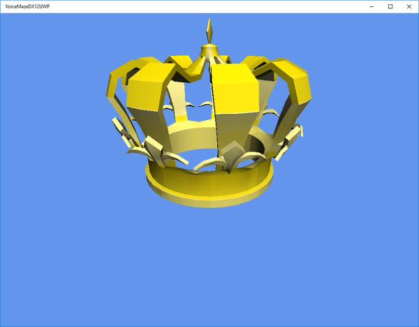
| We will be using this crown model as a player avatar. It was created and exported from 3D Studio Max |
5. VOICE MAZE
In this section we will go through parts that I would consider part of a concrete application implementation – in this case – the idea behind the Voice Maze.
5.1 Maze construction
First step is the maze itself. The easiest way to achieve the construction is to have a 2D array of integers that represents the composition of the maze. Certain numeric values represent certain maze elements:
[0] is an empty space
[1] is a wall
[-1] is the starting field
[-2] is the finish field
The construction of the maze is the responsibility of the Maze class. In its Initialize method we have the array representation of the maze and we populate the MazeElements array based on that data. Every single maze element is a specifically textured cube. The walls are raised by half the size of the cube so to give the illusion that the path of the maze is enclosed by the walls. We also have a failsafe inside the Initialize that checks if the provided data forms a closed maze – i.e. the maze cannot be walked out ant into nothingness by reaching certain outer elements. If this turns out to be the case, additional surrounding wall border is added.
void Maze::Initialize(ID3D12Device *d3dDevice, const Microsoft::WRL::ComPtr &commandList, ContentManager *contentManager)
{
	//maze array representation
	const int KMazeData[] =
	{
		0,0,0,0,0,-1,
		0,1,1,0,1,1,
		1,0,1,0,0,0,
		0,0,0,1,1,0,
		0,1,0,0,1,0,
		-2,1,0,0,0,0
	};
	int numCols = 6;
	int numRows = 6;

	//create the maze
	bool enclosed = CheckIfEnclosed(KMazeData, numRows, numCols);
	if (!enclosed)
	{
		m_mazeElementTypes.resize(numRows + 2);
		for (int i = 0; i < numRows + 2; i++)
			m_mazeElementTypes[i].resize(numCols + 2);

		for (unsigned int i = 0; i < m_mazeElementTypes.size(); i++)
			for (unsigned int j = 0; j < m_mazeElementTypes[i].size(); j++)
			{
				if (i == 0 || i == m_mazeElementTypes.size() - 1 || j == 0 || j == m_mazeElementTypes[i].size() - 1)
					m_mazeElementTypes[i][j] = 1;//set to a wall
				else m_mazeElementTypes[i][j] = KMazeData[(numRows-i )*numCols + j - 1];
			}
	}
	else
	{
		m_mazeElementTypes.resize(numRows);
		for (int i = 0; i < numRows; i++)
			m_mazeElementTypes[i].resize(numCols);

		for (unsigned int i = 0; i < m_mazeElementTypes.size(); i++)
			for (unsigned int j = 0; j < m_mazeElementTypes[i].size(); j++)
				m_mazeElementTypes[i][j] = KMazeData[(numRows-i-1)*numCols + (j)];
	}


	//create graphical elements
	m_mazeElementInstances.resize(m_mazeElementTypes.size());
	for (unsigned int i = 0; i < m_mazeElementTypes.size(); i++)
		m_mazeElementInstances[i].resize(m_mazeElementTypes[i].size());

	auto wallTexture = contentManager->Load(L"Textures\\walltex.png", commandList.Get());
	auto floorTexture = contentManager->Load(L"Textures\\floortex.png", commandList.Get());
	auto floorTextureS = contentManager->Load(L"Textures\\floortexS.png", commandList.Get());
	auto floorTextureF = contentManager->Load(L"Textures\\floortexF.png", commandList.Get());
	Texture* textures[] = { floorTextureF, floorTextureS, floorTexture, wallTexture};

	for (unsigned int i = 0; i < m_mazeElementInstances.size(); i++)
		for (unsigned int j = 0; j < m_mazeElementInstances[i].size(); j++)
		{
			auto type = m_mazeElementTypes[i][j];
			auto element = new MazeElement(d3dDevice, commandList, textures[type +2]);
			if (type == 1)
				element->SetPosition(DirectX::XMFLOAT3(j, 0.5f, i));
			else element->SetPosition(DirectX::XMFLOAT3(j, 0, i));
			m_mazeElementInstances[i][j] = element;

			if (type == -1)//start position
				m_startPosition = DirectX::XMFLOAT2(j, i);
		}
}
Now every render pass, all the elements in the array are run through and rendered forming the final maze.
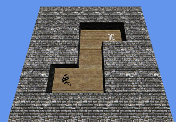
| A simple maze being rendered |
5.2 Game Logic
When the game is started or once the maze is being formed, to be precise, the starting position in the maze is recorded and player’s position is set to that value.
In the VoiceMaze in the Update method, once the input arrives an input sanitation is performed. We check the intended position against the integer values of the 2D array. If the input would result in avatar going into a space with a wall, we simply ignore it and wait for another command.
void Maze::ProcessInput(EInput input, PlayerAvatar *playerAvatar)
{
	if (playerAvatar->IsMoving())
		return;

	auto currPos = playerAvatar->GetCurrentPositionIndex();
	auto avatarY = playerAvatar->GetCurrentPosition().y;

	switch (input)
	{
	case EInput::EInput_DOWN://up down might seem inverted, this happens because of the way it's stored in the array
		if (currPos.y> 1)
			if (m_mazeElementTypes[currPos.y - 1][currPos.x] != 1)
				playerAvatar->MoveAvatar(DirectX::XMFLOAT3(currPos.x, avatarY, currPos.y - 1));
		break;

	case EInput::EInput_UP://up down might seem inverted, this happens because of the way it's stored in the array
		if (currPos.y < (int)m_mazeElementTypes.size() - 2)
			if (m_mazeElementTypes[currPos.y + 1][currPos.x] != 1)
				playerAvatar->MoveAvatar(DirectX::XMFLOAT3(currPos.x, avatarY, currPos.y + 1));
		break;

	case EInput::EInput_LEFT:
		if (currPos.x > 1)
			if (m_mazeElementTypes[currPos.y][currPos.x - 1] != 1)
				playerAvatar->MoveAvatar(DirectX::XMFLOAT3(currPos.x - 1, avatarY, currPos.y));
		break;

	case EInput::EInput_RIGHT:
		if (currPos.x < (int)m_mazeElementTypes[0].size() - 2)
			if (m_mazeElementTypes[currPos.y][currPos.x + 1] != 1)
				playerAvatar->MoveAvatar(DirectX::XMFLOAT3(currPos.x + 1, avatarY, currPos.y));
		break;
	}
}
After each movement completes we check if the current position is the finish space. If that is the case, we start the win sequence and reset the game. Otherwise the game continues on.
5.3 Movement and Animation
One closely related aspect to input and movement is the animation. Once the input is registered and the space to move into is valid one, we don’t immediately reposition the avatar to that spot. Instead, we start the transition animation which gradually moves the avatar to a new place in about 1 second.
This has two positive aspects. First, since we ignore any new input if the avatar is in move animation, we don’t need to add input delay. Without it a keypress would result in the model flying through the whole corridor to the nearest wall in the fraction of a second, because every update cycle the model would get repositioned to the next available spot that is indicated by the input direction. Another bonus is that the animated movement just looks nice to the human eye – if the objects are just jerking around from space to space it looks unnatural and plain weird.
In case the player reaches the final space a PlayEndAnimation method is called on the PlayerAvatar object. This plays a small animation by calling WinAnimationUpdate instead of the normal Update method on the PlayerAvatar. In essence the mesh is risen by a certain amount on the Y axis at the same time shrinking it to zero in scale. Then the mesh travels to the starting location and once over it, plays the same animation in reverse – scales it back to a normal size and lowers it on the Y axis. Since the camera is always following the player we get this nice, simple transition between a win state and a new game.
5.4 Input
Input is your actual interaction with the application. Without it you would not be able to control anything that is happening on the screen. Even though there are applications that don’t need any actual input – like a 3D demonstration or benchmark tools, most of the time you would want to give the user the ability to interact with your game\application.
In Voice Maze we have two options for user input – speech recognition and keyboard input. Both of them are encapsulated by the MazeInput class, which will first try to get the input from speech recognition and then fall back to keyboard if nothing was recognized.
5.4.1 Voice input

We will be using VoiceInput class to process the input data and provide us a unified movement direction.
When initializing, we supply it with the dictionary of words we would like our application to react on. These are called the Input Constraints.
VoiceInput::VoiceInput()
{
	m_recognitionConstraints = ref new Vector();

	IVector ^directions = ref new Vector;//array of voice commands to listen for

	directions->Append("up");
	directions->Append("down");
	directions->Append("left");
	directions->Append("right");

	SetInputConstraints(directions);
}
void VoiceInput::Start()
{
	m_isActive = true;
	m_lastReadingValue = L"";

	m_speechRecognizer = ref new SpeechRecognizer();
	auto listConstraint = ref new SpeechRecognitionListConstraint(m_recognitionConstraints, L"TextTagIdWhatever");

	m_speechRecognizer->Constraints->Append(listConstraint);

	auto constraintsCompilationTask = create_task(m_speechRecognizer->CompileConstraintsAsync());

	constraintsCompilationTask.
		then( [this](SpeechRecognitionCompilationResult ^compilationResult)
		{
			StartRecognitionInstance();
		}
	);
}
The actual recognition is done asynchronously on another thread. When VoiceInput::Start is called, we first initialize a new SpeechRecognizer and also create a SpeechRecognitionListConstraint object from our constraint dictionary which is then supplied to the SpeechRecognizer instance. This data is then prepared for the recognition with the CompileConstraintsAsync task. Once it completes, we are ready to start the recognition itself.
void VoiceInput::StartRecognitionInstance()
{
	auto recognitionTask = create_task(m_speechRecognizer->RecognizeAsync());
	recognitionTask.then([this](SpeechRecognitionResult ^recognitionResult)
	{
		auto newValue = recognitionResult->Text;
		m_lastReadingValue = newValue;
		if (IsActive())
			StartRecognitionInstance();
	});
}
When we call VoiceInput::StartRecognitionInstance a new task is started which will gather live input sound from the microphone and will try to make sense of that data by matching it with the Input Constraints. The result will be stored in SpeechRecognitionResult Text member. After one recognition cycle completes, we immediately start a new one by calling StartRecognitionInstance again.
Platform::String^ VoiceInput::GetLastReading(bool clearValue)
{
	auto readingValue = m_lastReadingValue;
	if (clearValue)
		m_lastReadingValue = L"";

	return readingValue;
}
Every Update cycle in the main VoiceMazeRenderer::Update method we will ask the VoiceInput instance whether or not it has some new data for us. When we call GetLastReading, the last recorded and recognized input text will be provided and the data will be cleared. We can compare the string to the expected values and move the avatar accordingly. In case no new data arrived, the method will return an empty string and no action will take place.
bool MazeInput::ProcessVoiceInput()
{
	bool inputReceived = false;

	auto lastVoiceCommand = m_voiceInput.GetLastReading(true);
	if (lastVoiceCommand->Equals("up"))
	{
		m_lastInput = EInput::EInput_UP;
		inputReceived = true;
	}
	else if (lastVoiceCommand->Equals("down"))
	{
		m_lastInput = EInput::EInput_DOWN;
		inputReceived = true;
	}
	else if (lastVoiceCommand->Equals("left"))
	{
		m_lastInput = EInput::EInput_LEFT;
		inputReceived = true;
	}
	else if (lastVoiceCommand->Equals("right"))
	{
		m_lastInput = EInput::EInput_RIGHT;
		inputReceived = true;
	}
	else m_lastInput = EInput::EInput_NONE;

	return inputReceived;
}
5.4.2 Keyboard input
Keyboard input is quite simple if compared to the Speech recognition. The low-level state is handled inside the GameInput class. We will only be reacting to key presses that happen on the game’s window. So we get the main window instance:
m_coreWindow = Windows::ApplicationModel::Core::CoreApplication::GetCurrentView()->CoreWindow;Once the Update phase arrives, we poll each key we are interested in: in our case up, down, left and right arrow keys and check their statuses.
bool GameInput::IsKeyPressed(Windows::System::VirtualKey key)
{

	auto result = m_coreWindow->GetKeyState(key);
	return (int)result & (int)Windows::UI::Core::CoreVirtualKeyStates::Down;
}
If any of them are pressed down, well we react as was the case with the voice input.
void MazeInput::ProcessKeyboardInput()
{
	if (m_gameInput.IsKeyPressed(Windows::System::VirtualKey::Up))
		m_lastInput = EInput::EInput_UP;
	else if (m_gameInput.IsKeyPressed(Windows::System::VirtualKey::Down))
		m_lastInput = EInput::EInput_DOWN;
	else if (m_gameInput.IsKeyPressed(Windows::System::VirtualKey::Left))
		m_lastInput = EInput::EInput_LEFT;
	else if (m_gameInput.IsKeyPressed(Windows::System::VirtualKey::Right))
		m_lastInput = EInput::EInput_RIGHT;
	else m_lastInput = EInput::EInput_NONE;
}
GENERAL CODE\ENGINE STRUCTURE
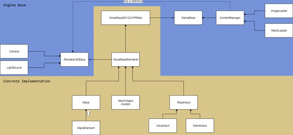
| Diagram indicates the overall structure of the project and the component relations |
CONSIDERATIONS, FURTHER STEPS
There are quite a few areas of improvement as far as this project goes. From my standpoint, I would start with Shadow Maps, Instancing and overall base structure optimization.
Shadow Maps is the current de facto standard when it comes to shadow rendering. You might have noticed that the project might feel a bit weird – the objects react to the light naturally, their sides get darker or brighter depending on the source of the light, but one crucial part is missing. No object is casting shadows on other objects.
The shadows are a natural part of our world. We take them for granted. But when there are no shadows we instantly feel that something is not right with the picture. We might not be able to put our finger on it, but it really bothers us. This is because shadows carry a very important information – they tell you how objects are sitting in space in relation to each other. If an object is right on the surface – it casts a really strong but small shadow. As it starts moving towards the light source – the shadow starts to get bigger and blurrier. That is how we perceive it, even without ever noticing it consciously.
This is especially noticeable in our application when the crown mesh starts to rise and shrink. If you know what is supposed to happen you can sort of feel it. But to others it looks really weird, and some people might not even be able to tell what is going on exactly.
Shadow maps, in short, render the whole scene from the perspective of the light source. Only the depths are rendered into a separate buffer. Once this is completed – a normal rendering pass from the point of the camera takes place. When the shader runs, every pixel that is about to be rendered is checked against the rendered depth texture. If we calculate that the pixel-to-be-rendered is blocked from the light source by some other geometry, we color it darker – it is in shadow. This way we simulate shadows without too much overhead. Most of the games and applications today employ shadow maps for their needs in one form or the other – the algorithms might be a lot more complex, but the general idea behind it is the same. You can find more info about shadow maps in the links section.
Instancing is another optimization technique. Currently, all maze elements are actual 3D objects with their own geometry that is uploaded to the GPU even though the textures are shared. One of the ways we could save on some memory and processing is by reusing the same geometry for all the elements of the maze – just transforming to required positions and applying the necessary texture. The way the constant buffer data is sent in and versioned would need to be refactored but would be a more “environment friendly” approach.
Structure optimization is pretty straightforward. As you move on creating your game – the needs and therefore the base structure will change. Even for this demo project the initial architecture changed a couple of times and when doing the structure diagram, I noticed quite a few points of improvement: for example, the shared ContentManager reference immediately catches the attention as it is doing something not entirely right. So, when you are coding your project, don’t be afraid and refactor often – things change rapidly from the first time you encounter them, that is just the way it is.
LINKS \ FURTHER READING
RB Whitaker’s Wiki. I really think this guy does not get enough credit as he is such a mentor to a lot of us out there. Especially good starting point if you do XNA \ MonoGame development
My old article if you are interested (targets DirectX 10 – 11):
HLSL Tools for VS by Tim G. Jones, if you’ve missed it before:
Albeit a bit outdated (DirectX 11.2 is the latest one covered), this page it still is a good read to get introduced to DirectX. Provides great examples and is really easy to follow. And, heck, even though DirectX 12 is the hot topic right now, it does not mean the older versions are no longer supported.
A really nice tutorial page. A shame I found it a bit too late.
ImageLoading process described in detail and many other goodies.
A different take on UWP DirectX application albeit in DirectX 11 can be found here.
Here’s an outstanding D3D12 project from Microsoft, a really nice and noteworthy to look through.
THANKS
I would like to thank my long-time collaborator Martynas Pikiotas for the nice hand coordinates and the lightbulb illustrations.
CONCLUSION
This article showed you how to initialize devices, set up the environment and start drawing 3D objects on screen. Furthermore we learned about the 3D basics, how to texture, add lighting and load 3D model files. In the end we had a project that was drawing a maze that could be navigated using speech commands or your good old keyboard. The project should provide you an idea of what a game engine is and how you would go about creating one on your own.
Even though this example project is a far cry from a decent engine, it should serve as a good starting point to creating your small DirectX 12 enabled project.
SOURCE
The project source can be found here.